
L
Laura TylerAug 15, 2025
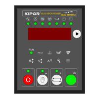
What to do if Kipor Controller has a start failure?
- SSean YoungAug 15, 2025
If the Kipor Controller fails to start, begin by inspecting the fuel pipe and its connections. Next, check the batteries. Also, examine the RPM sensor and its connections to ensure they are properly configured.