TM840 Service Manual
(4V<VOH<5V,0V<VOL<0.4V)
21 Prgm_IO_4(Emergency) Programmable I/O 4
(Emergency)
Programmable I/O
(2.5V<VIH<5V,0V<VIL<0.4V)
(4V<VOH<5V,0V<VOL<0.4V)
22 Prgm_IO_8 Programmable I/O 8 Programmable I/O
(2.5V<VIH<5V,0V<VIL<0.4V)
(4V<VOH<5V,0V<VOL<0.4V)
23 Ign_Sense Ignition Sense (10V<VIH<16V,0V<VIL<2V)
24 Prgm_Out_9(Ext_Alarm) Programmable I/O 9 (External
Alarm)
Programmable I/O
(2.5V<VIH<5V,0V<VIL<0.4V)
(4V<VOH<5V,0V<VOL<0.4V)
25 Aux_Audio_Out1 Auxiliary Audio Output 1 (Wmax=15mW@32Ω)
26 Aux_Audio_Out2 Auxiliary Audio Output 2 (Wmax=15mW@32Ω)
Table 2 PIN Definition of Seconde Development Interface
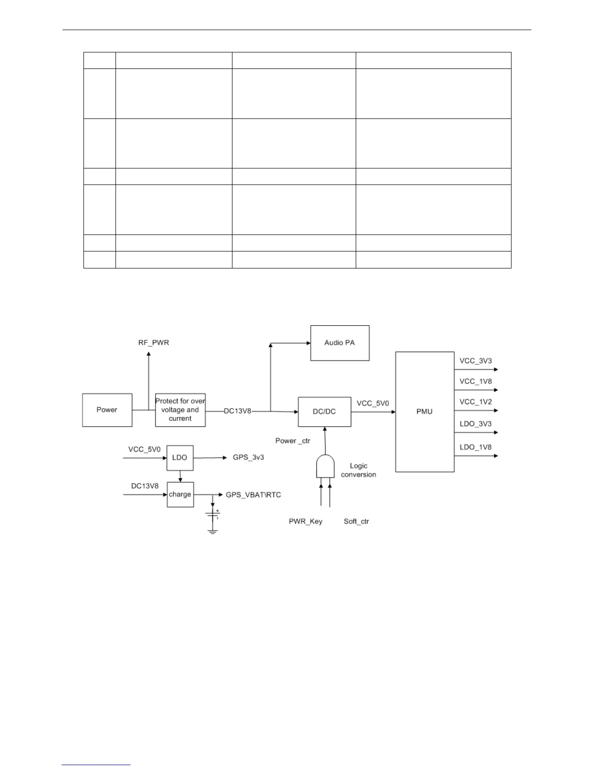
3.2.2 Power Section
Figure 3.7 Power Section Diagram
This radio employs vehicle-mounted power supply, baseband and RF circuit use indepent power supply, which equipped
with power supply protection unit in the power supply front end to protect the back end circuit when detecting the over loaded
voltage and current situation. Baseband power supply uses two stages switch circuit. The first stage will decrease the power
supply voltage to 5V by DC/DC, then the second stage will switch the 5V to the power what the system needs via power
management module.
Radio on/off: The radio controls the DC/DC enable end to achieve the radio on and off. When power button is on, the logic
electrical level of PWR_Key is low. The high electrical level will be output through the logic switch circuit, then the DCDC
circuit can be enabled to run the system.
10

 Loading...