TM840 Service Manual
board.
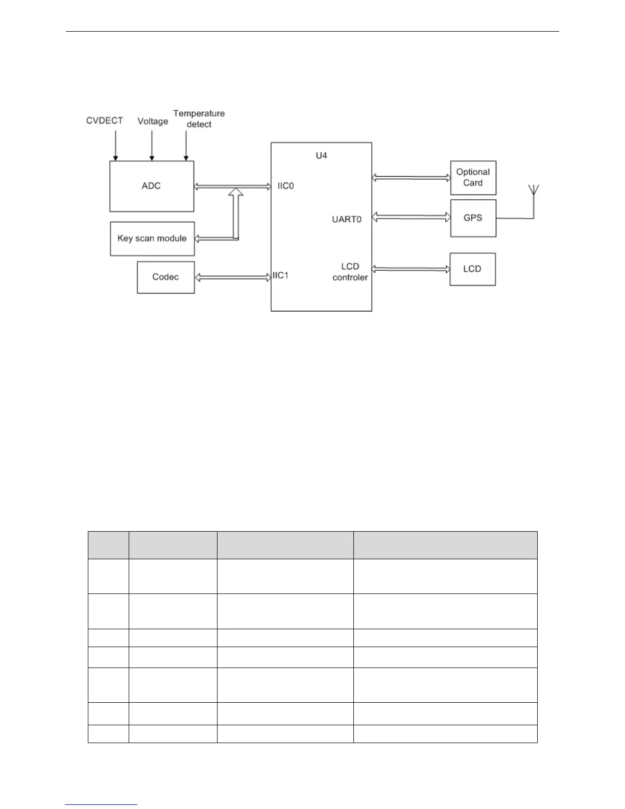
(2) System Peripheral Functions Module
Figure 3-9 System Peripheral Diagram
This system includes: ADC module, optional board interface module, display module, keypad detection module and GPS
module. These modules are used to achieve human-radio interaction, radio status detection, communication encryption and
extension functions. ADC is mainly used to detect the radio power supply, temperature, which achieves low battery alert and
temperature controlled. GPS is for positioning the radio’s position. Optional board module is to achieve extension functions
to meet users further demands.
3.2.4 Control Panel
The control panel is to achieve human-radio interaction functions. The control panel includes display, key scan, volume
control, status indication and accessories interface.
Front Mic Pin-Out Definition:
Pin Signal Name Function Signal Definition
1 Key_DATA Mic Keypad Data Line
Digital Input
(2V<V
IH
<3.3V,0V<V
IL
<0.8V)
2 HOOK Mic Hook Indication
Digital Input
(2V<VIH<3.3V,0V<VIL<0.8V)
3 MIC+ MIC+ Analogue Input (VIN<2.0V)
4 MIC- MIC- Analogue Input (VIN<2.0V)
5 PTT PPT Key
Digital Input
(2V<VIH<3.3V,0V<VIL<0.8V)
6 GND Ground Power Ground
7 POWER Mic Power Supply (7~12V) Power Output (7~12V)
12

 Loading...