Page 6
Preparing for Installation
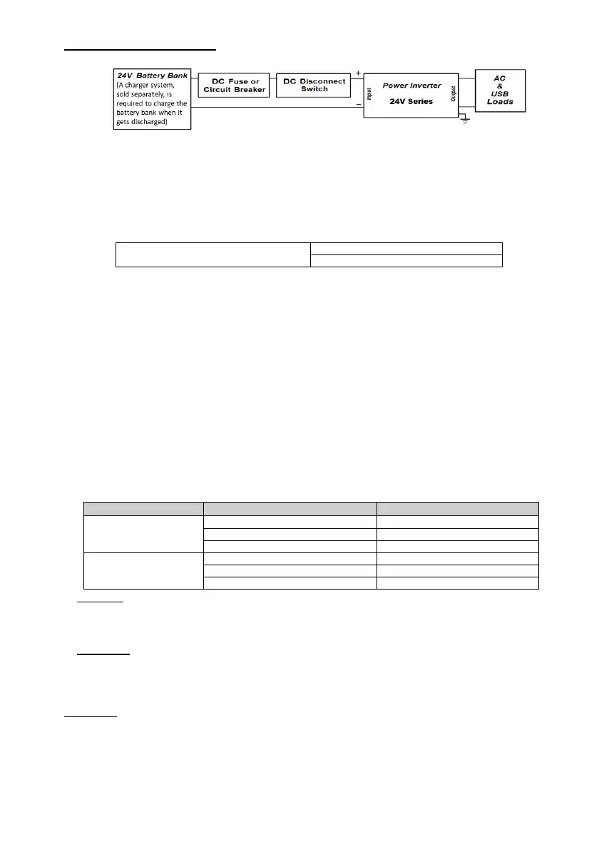
Typical Wiring block diagram of charger:
24V Battery Bank:
• The use of a deep cycle battery is highly recommended for power inverter application
• For battery sizing, you need to identify how much and for how long the inverter has to provide AC
power to the loads (based on Amps x hour energy consumption). It is recommended to purchase
as much battery capacity as possible. See more in “Estimated Run Time” section 4.
DC Fuse or Circuit Breaker:
• A DC-rated fuse or DC-rated circuit breaker connected along the DC positive line is required.
Fuse/Circuit Breaker Rating
• Based on the size of your 24V Battery Bank, determine the overall short circuit current rating of the
battery bank from the battery manufacturer. The fuse or circuit breaker has to be able to withstand
the short circuit current that can be generated by the battery bank. Typically, an ANL/Class-T fuse
& holder is used.
• For Marine applications, the over-current protection device (either DC fuse or DC breaker) needs
to be installed within 7 inches (18cm) from the battery positive terminals.
Battery Disconnect Switch:
• Use a 24V battery Disconnect Switch (on the positive) with the same or higher rating as the
selected fuse or circuit breaker. Use ignition protected switches when required by local codes.
• The purpose of this switch is to disconnect the positive in between the unit and the battery bank
during maintenance or repair service, when not in-use, or when troubleshooting. It could also be
an A / B / A+B / OFF type switch to select either one of two or both (paralleling) battery banks (if
available).
DC Input Wires Gauge and Length:
• All DC wires should be insulated multi-strand low resistance ones.
• The DC wires must be copper and rated 105℃ minimum.
AWG # 8 (typical & suggested)
AWG # 2 (typical & suggested)
Caution: The use of a thinner gauge in the DC wires may cause the inverter to trigger the under-
voltage shut down under heavy load conditions. It may also melt the wire insulation and catch fire,
resulting in death or serious injury. The choice of the wire gauge should also match or exceed the
ampacity rating of the DC fuse being used.
Important: The typically recommended wire length is limited to 5 feet or less for each of the positive
and the negative. For longer wires, a proportionally thicker gauge is required to compensate for
additional voltage drop (see the above table).
Chassis Grounding Wire Size:
Important: The chassis of the unit has to be grounded through the corresponding stud terminal (with
nut and washer) located near the DC negative terminal. Use it for both DC and AC grounds.
• For Marine applications, the DC grounding wire gauge can be one size thinner than the minimum
size required for the DC current-carrying conductors (i.e. positive and negative) and never thinner
than AWG #10 (as long as the mandatory DC+ fuse is used).
• For Recreational Vehicle or Caravan applications, the unit has to be grounded to the vehicle
chassis with AWG #8 or thicker copper conductor.
 Loading...