Page 7
Installing the Power Inverter System
WARNING: Electrical Shock Hazard
The unit ‘On/Off’ push button does not disconnect the DC power from the battery. Use the
external battery switch or remove the DC input wires to disconnect the DC power from the
battery before working on any AC appliance or hardwired circuits connected to the unit.
Failure to follow these instructions can result in death or serious injury.
Installation:
• Choose an appropriate indoor mounting location.
• The unit can be mounted in any direction except with the DC Input panel facing downwards.
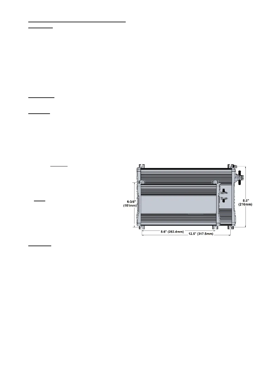
• Use the mounting template on the right to mark the positions of the mounting screws.
• Drill the 4 mounting holes and place the Power Inverter in position and fasten the unit to the
mounting surface.
Important: The wire tightening torque on the DC terminal nuts should be 12-13 Nm
Chassis Grounding Connection:
DANGER: The unit chassis has to be grounded properly. Never operate the Power Inverter
without proper grounding. Failure to do so will result in death or serious injury.
• Connect the grounding’s ring terminal to the unit’s ground stud terminal (with nut and washer)
using the wire gauge as explained above.
• Connect the other side of the wire to the main DC grounding point (e.g. engine block, battery
negative terminal, vehicle chassis, etc.). The main AC grounding point in the AC system should
also be connected to the main DC grounding point* by a separate wire with a gauge no thinner
than the one of the Hot and Neutral coming from the shore power main plug. Even though the
chassis ground is bonded to the battery negative (either directly or through a main DC grounding
point), NEVER use the DC negative
terminal of the unit to connect the
chassis ground with a short jumper.
The AC and DC chassis ground of the
unit must use a separate and
dedicated non-carrying-conductor.
Note *: In marine applications, the
main AC-DC ground bonding may
require galvanic isolators to avoid
galvanic corrosion. Check your local
electrical codes (i.e. NEC, UL,
ABYC...).
DC Input Connection:
CAUTION: Reversing the DC Input terminal will damage the unit and it cannot be repaired.
Damage caused by reverse polarity connection is not covered by the warranty.
• Connect the Inverter DC negative terminal directly to the battery negative terminal.
• Make sure the DC Disconnect Switch in the positive is in the OFF position.
• Connect the inverter DC positive terminal to one terminal of the Disconnect Switch. Then, connect
the other terminal of the Disconnect Switch to one of the terminals of the fuse holder.
• Connect the other terminal of the fuse holder to the battery positive terminal. Most standards
require this wire be no longer than 7 inches.
• Install the suggested fuse to the fuse holder, and turn on the battery disconnect switch.
Remote Switch (optional) Connection:
• Plug the Remote Switch accessory (RM1201-00) into the RJ11 (phone type jack) of the ‘Remote
Switch Port’, located on the front panel of the unit. It is a momentary-on switch that connects in
parallel to the “Power/Select” pushbutton on the front panel.
Test the Power Inverter connection and operate the unit:
• Turn the unit on by pressing and holding the Power/Select button until hearing a beeping sound
(in about 1 sec.). Then, release your finger, and the unit starts a 7 sec. initiation period with the
display showing “rx.x” (the panel software version) then “ux.x’ (the main unit software version), with
 Loading...