2
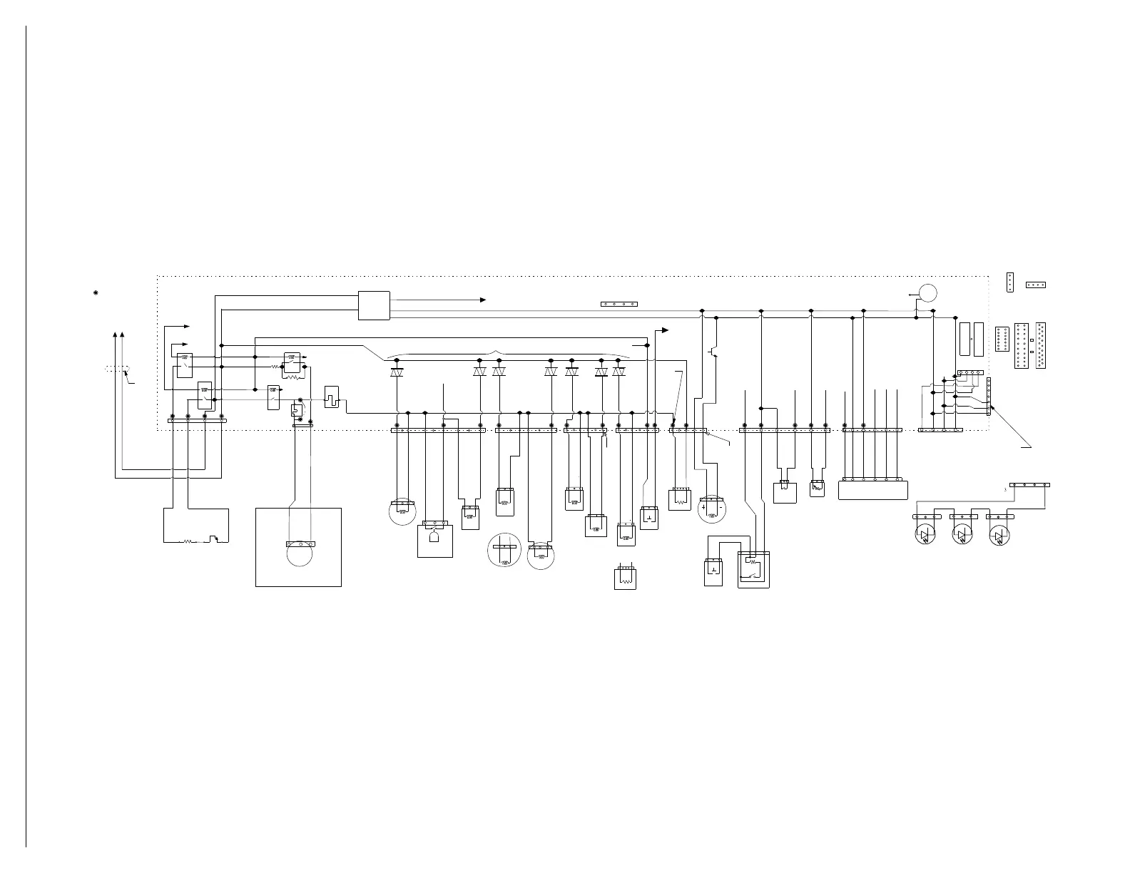
Wiring Diagram
Schematic shown with door switch and all other normally open contacts open.
*Denotes energy-efficient components. Do not substitute.
Most used test points on
PC board for multimeter
checks.
N
WH
BK
Ferrite
(1 Loop)
BK
WH
Heater
Element
Thermostat
(Hi-Limit)
BU/R
BU-R
N.C.
Micro Pin
K1
HTR-N
Relay
K3
HTR-L
R
elay
P4
P4-4
P4-3
P4-2
P4-1
BK
WH
K4
Sense
Motor
Relay
Optional
P5
F9
Fuse
P5-2
P5-1
LB
LB
L1
N
3
2
1
1 - PH Sync
Wash
Motor
Pump
Drain
Motor
1
3
3
3
3
3
1
1
1
Overfill
(Float)
Switch
Fill Valve
*
Softener
Regen Valve
(Not All
Models)
Diverter
Motor
1
3
1
3
1
3
1
3
1
31
3
1
2
1
3
1
2
3
4
3
1
3
1
3
1
2
4
5
6
(Spare)
(Spare)
Future
Future
Vent Wax
Motor
Fan Motor
Optional
Flow
Meter
39K
Softener
Salt Sensor
(Closed When
Empty)
(Not All Models)
Diverter
Position
Switch Contact
(Closed During
Tr an s it i on s )
(Spare)
Future
O.W.I*
(NTC, Foam, & Turbidity Sensor)
BR
BR
BR
BR
B
R
BR
BU
BU
BU
BU
RD
RD
RD
RD
V
V
V
V
BR
BR
BR
BR
13V
VCC
REF
(+8V)
(N)
(-5V)
7P6P
P8
P9
P10
P11
P12
P13
3
Door Open Detection
P2
12
3
4
13V
Pilot L1
Te s t
Pad For
All
Tr i ac
Loads
Fan Load
(Current)
Sense
Analog
Input
Digital
Input
Analog
Input
NTC
Input
Opt
Sig
Foam
Drive
Tu r bo
Drive
13V
VCC
Wide
Data
13V
Beeper
REF
VCC
Wide Data
P1A
P1B
LED
Displays
14-pin
Mechanical
Push-Button
Boards
20-pin
Active
Overlays
19-pin
ZIF
1
3
2
4
5
6
7
Black Stripe On Connector
Red
Stripe On Connector
P6-1
P6-3
P6-4
P6-6
P6-7
P6-9
P7-1
P7-3
P7-4
P7-6
P8-1
P8-3
P8-4
P8-6
P9-1
P9-3
P9-5
P9-6
P10-1
P10-3
P10-5
P10-4
Micro Pin
Micro Pin
Micro Pin
K2
F8
Fuse
Or
51
Dispenser
Wax Motor
P13-1
P13-2
P13-3
P13-4
LCD UI
4-pin
Pilot
Relay
W2
P11-3 RD
P11-3 RD
P11-2 RD
P11-4 RD
P11-5 RD
P11-6 RD
P12-1 YL
P12-2 YL
P12-3 YL
P12-4 YL
P12-5 YL
P12-6 YL
Dispenser
Solenoid
Door Switch
On some models
Te m p o r a r y
Connection Port
for Development
To o l s ( & f u t u r e
service tools)
P1A and P1B
User Interface
Connector Options
Capacitive Touch
Keyboards 4-pin
P1-VCC
P4-REF
Electronic Control* CCU1
PC Board 190.28 x 81.01 mm
2-sided FR4
Power Supply
Level 1-3W
Level 2-4.4W
Level 3-7.4W
Motor Sense circuit
is different for
High vs Low Power motors
Return Line 13 Volt relay coils go through Door Switch
AC Input
Overfull/Leak Detection
(and Pilot Relay detection)
Load (current) Sense for drain, vent and all other triac loads on Pilot
In Factory programming port
(on top surface of PCB)
(Depopulate in production; use pads)
CR-
1
BU/WH
BU/RD
1
23
4
P1C
L1
1
2
3
1
2
3
1
2
3
1
2
3 4
Light
Light
Light
To Connector P13
Light In tub
(on some models)
GY
GY
3
1
Fan Motor
or