4
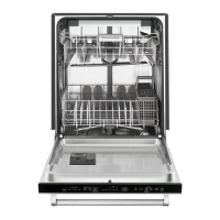
Control Pinout
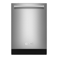
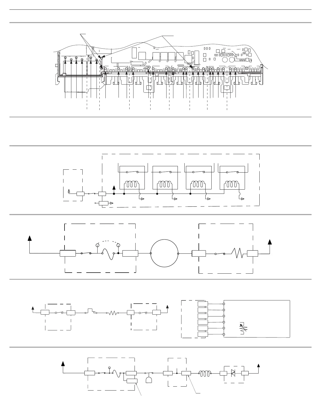
Meter Check of Loads and Fuses
Dishwasher Strip Circuits
The following individual circuits are for use in diagnoses. Do not continue with
the diagnosis of the appliance if a fuse is blown, a circuit breaker is tripped, or if
there is less than a 120-volt power supply at the wall outlet.
■ Unplug dishwasher or disconnect power.
■ Perform resistance checks. To check resistance of a component,
disconnect harness leads first.
Door Switch
Wash/Rinse
Water Heating/Heat Dry and Water Sensing with O.W.I. Sensor (Water/Air/Soil/Temperature)
Pump is washing and control monitors temperature during water heating periods. See “Wash/Rinse” and “Water Sensing with O.W.I. Sensor (Water/Air/Soil/
Te m p e ra t u re ) ” c irc ui ts .
Fill
(Top)
W2
P5
P6
P7
P8 P9
P10 P11
P12
P13
-4
-3
-2
-1
-2
-1
-1
-6
-9
-1
-6
-1
-6
-1
-5
-6
-1
-3
-5
-1
-2
-4
-6
-1
-3
(OWI)
P12
(Wide Out)
P13
P4 P5
P6
BR
P7
BU
P8
RD
P9
V
P10
BR
P11
RD
P12
YL
Ω
of F9 Triac Fuse
Ω
of F8 Motor Fuse
Electronic Control
Electronic Control
Micro PinMicro Pin
Micro PinMicro Pin
K4
Motor (N) Relay
K3
Heater (L1) Relay
K2
Pilot (L1) Relay
K1
Heater (N) Relay
N.O. N.O. N.O. N.O.
(To Wash Motor)
(To Heater)
(To Wash Motor,
Vent, and Triac Loads)
(To Heater)
N.O.
Door
Switch
Sensing
Input
Ref
P9-5
P10-4
Door
Switch
P9-6
13V
VV
Motor Power
Sense
Resistor
or Jumper
0
Ω
L1
BK
P4-2
P5-2
P5-1
P4-1
N
WH
K4
Motor N Relay
(Also see Door
Switch Circuit)
N.O.
1-PH Sync
Wash Motor
(Power Supply)
Electronic Control
Electronic Control
Pin 3
Pin 2
120V, 60 Hz
5-15
Ω
, 60W
Fuse
F8
K2
Pilot L1 Relay
(Also see Door
Switch Circuit)
Use holes of jumper
W2 as test points for F8.
(Top Hole)
(Bottom
Hole)
N.O.
W2
(LB)
TURQ
TURQ
(LB)
L1
BK
Electronic Control
N.O.
K3
Heater L1 Relay
(Also see Door
Switch Circuit)
Hi-Limit
Thermostat
Opens
207°F - 217°F
(97°C - 103°C)
Heater Element
8
Ω
- 30
Ω
120V, 60 Hz
Plastic Models:
805W Wet / 385W Dry
Stainless Steel Models:
785W / 500W Dry
N.C.
P4-2
P4-3
BU/RD
BU/RD
BU/WH
P4-4
P4-1
WH
N
Electronic Control
N.O.
K1
Heater N Relay
(Also see Door
Switch Circuit)
Electronic
Control
P12-6
P12-5
P12-4
P12-3
P12-2
P12-1
YL
YL
YL
YL
YL
YL
Pin 1
Pin 2
Pin 3
Pin 4
Pin 5
Pin 6
Measure NTC resistance at P12-1 and
P12-3 connector disconnected from control.
Turbidity Drive
Foam Drive
OPT Sig
VCC
Ref
NTC
O.W.I. Sensor
Temperature: NTC Thermistor
46K
Ω
- 52K
Ω
at 77°F (25°C)
11K
Ω
- 13K
Ω
at 140°F (60°C)
Heater
L1
BK
P4-2 P6-4
P10-1
P6-6
P6-7
P6-9
P4-1
Use top hole of jumper
W2 as test point for F9.
N.O.
K2
Pilot L1 Relay
(Also see Door
Switch Circuit)
Fuse
F9
Electronic Control
Electronic Control
Float
(In normal position,
holds switch closed.)
BR
BR
N.O.
Pin 3 Pin 1
Overfill
Float Switch
No test pad on P6-4.
Recommend using test pad on P10-1.
No test pad on P6-7.
Recommend using test pad on P6-6.
Electronic Control
Float Switch
Input
BR
BR
Pin 3 Pin 1
Triac
Fill Valve
890
Ω
- 1,600
Ω
120V, 60 Hz, 6W
WH
N