3
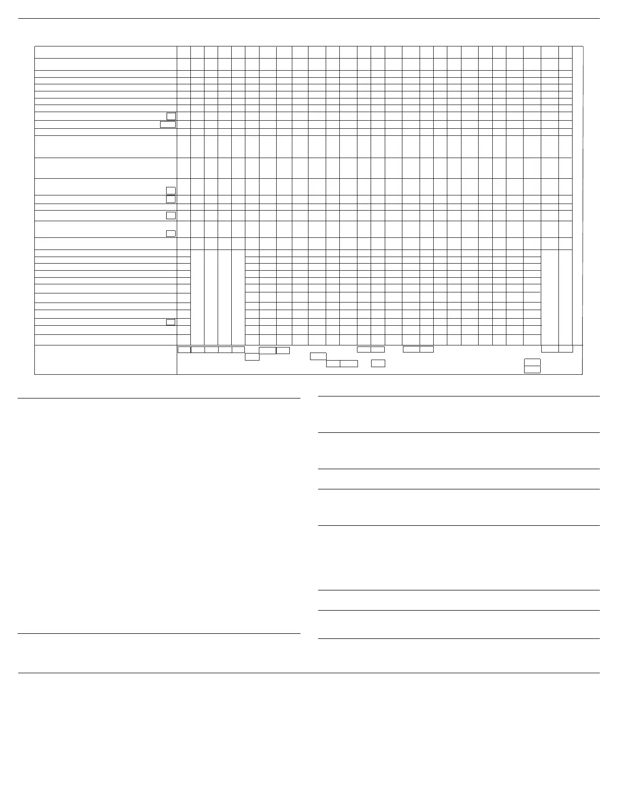
Service Diagnostics Cycle
Service Diagnostics Cycle Notes:
Customer Cycle Operation
To q ui c k l y adv an c e thro u g h customer cycles, invoke the Rapid Advance
mode by pressing HIGH TEMP - HEATED DRY - HIGH TEMP - HEATED DRY,
after starting the cycle. Then, press START/RESUME to advance through
cycle intervals.
NOTE: Rapid Advance mode is automatically enabled in the Service
Diagnostics cycle but must be manually invoked in customer cycles.
26
25 24 23
22 21 18
17
16
15
14
13
12
11
10
9
8
7
65 4 3
2
1
INTERVAL
CYCLE, OPTION, AND STATUS LEDs
NORMAL
HI TEMP
DRY OPTION
1 HR WASH
START/RESUME
RUNNING (Front Status light)
SANITIZED
CLEAN/ 7-Seg
ALL OTHER CYCLE, OPTION, AND STATUS LEDs
NRM
NRM
NRM
NRM
NRM
NRMNRM
NRM
NRM
NRM NRM
NRM
HITHIT
HIT
HITHIT
HITHIT HIT
HIT
HIT
HIT
HIT
DRY
DRY
DRY
DRY
DRY
DRYDRY
DRY
DRY
DRY
DRY
1HR
1HR
1HR
1HR 1HR
1HR
1HR
1HR 1HR 1HR
1HR
1HR
STA
STA STA STA
STA
STA
STA
STA STA
STA STA
STA
STA
STA
STA
STA STA STA STA STA
STA
STA
STA
RUN
RUN
RUN RUN
RUN RUN
RUN
RUN
RUN
RUN
RUN
RUN
RUN RUN
RUN
RUN
RUN RUN
RUN RUN
RUN
RUN RUN
RUN
SAN
(SAN)
(SAN)
CLN
7-Seg
(CLN) (CLN)
ALL
NOTE
5
4,5,6NOTES
INTERVAL TIME (min:sec)
TOTAL TIME (MAX.): 22:57
SOIL SENSING INTERVALS
AND SENSOR CHECKS
NOTE
5
OWI (SOIL SENSOR) CHECK INTERVALS
NOTE
6
NOTE: OWI has thermistor built in - see check above
THERMISTOR (TEMPERATURE SENSOR)
CHECK INTERVAL
NOTE
8
SALT LEVEL REED SWITCH/
FLOWMETER INPUT TEST
LOADS
PILOT RELAY
VENT
FILL
WASH MOTOR
DISPENSER (DETERGENT/RINSE AID)
DRAIN MOTOR
DC FAN MOTOR (IF PRESENT)
HEATER
REGEN (IF PRESENT)
0:06
0:08
0:08
0:08
0:08
0:10
0:05
0:23
0:05
1:00
2:00
0:30
1:00
0:30
4:00
0:01
0:01
0:01
0:01
1:52
0:06
2:30
0:08
0:08
OWIOWI
THR
PLT PLT
PLT
PLT
PLT
PLT
PLT PLT PLT
PLT PLT PLT
PLT PLT PLT PLT
VNT
VNT VNT
VNT
VNT
VNT
VNT VNT VNT VNT
VNT
VNT
VNT
VNT
VNT VNT
FIL FILFIL
WSH
WSH WSH
WSH WSH
WSH
WSH
DSP
DRN DRN
DRN
FAN
HTR HTR
REG
2
CUSTOMER ERROR 1
CUSTOMER ERROR 2
CUSTOMER ERROR 3
CUSTOMER ERROR 4
SERVICE ERROR 1
SERVICE ERROR 2
S
T
A
N
D
B
Y
1
1
8
19
NRM
DRY
STA
RUN
(CLN)
0:44
4
5
HIT
HIT
PLT
VNT
DRN
S
T
A
N
D
B
Y
1
1
1 1
6 6 6
1HR
STA
SRM
NOTE
7
DIVERTER POSITION SENSOR CHECK
NOTE
3
DIVERTER
DIVERTER POSITION
DIV
(DIV) (DIV)
(DIV) (DIV)DIV
UPR
UPR
UPR UPR
UPR UPR UPRON
LOWLOW
LOW LOW LOW LOW
LOWTZ
FAN FANFAN
3
3 3
3 3
7
20
1HR
STA
RUN
(CLN)
9
0:01
HIT
7-Seg
7-Seg 7-Seg
7-Seg
7-Seg
AC FAN MOTOR (IF PRESENT)
1 To i nv o k e the Di a g nostics cy c l e , p e rfor m t h e f o llowing wh ile
in standby:
■ Press any 3 keys in the sequence 1-2-3-1-2-3-1-2-3 with no
more than 1 second between key presses.
■ The Service Diagnostics Cycle will start when the door is closed.
■ To r a p i d a dvance 1 in te rval a t a time, pre ss t h e S tart/Resu me k ey.
Rapid advance may skip sensor checks as some checks require
2complete intervals.
NOTE: While you are in the Diagnostic Cycle, the Start/Resume
feature is turned Off (for example, Auto Resume after door interrupts)
and the Start/Resume key becomes an interval advance key.
■ Invoking Service Diagnostics Cycle clears all status and last run
information from memory and restores defaults. It also forces the
next cycle to be a Sensor Calibration cycle.
■ Drain and wash motors will pulsate on and off.
■ Last run cycles and options returned to default.
■ Last run delay returns to the lowest delay increment.
■ Calibration cycle may force an extra rinse to occur prior to Final
Rinse (to assure clear water), then calibrates the O.W.I. and the fill
amount during the final rinse.
■ Operating state returns to Standby upon completing or
terminating the Service Diagnostics Cycle.
■ Reference the “Service Diagnostics with Error Codes” section
for details.
2 Tur n on a ll LEDs i mm ed ia te ly upon receiving the entry sequence (even
if the door is open) for 5 seconds as a display test. Turn off all LEDs for
1 second prior to reporting customer error history.
3 Diverter will be on continuously in interval 14. In all other diverter
intervals, diverter will be on only until it reaches the intended position
for that interval.
4 Press HI TEMP key in this interval to clear customer error history.
5 Thermistor (temperature sensor) checks - turn clean LED on if
thermistor is in its normal temperature range 32°F to 167°F (0°C to
75°C). Turn sanitized LED on if fill temperature is above 65°F (18.3°C).
6 OWI (optical soil sensor) checks:
■ Check OWI sensor for the presence of water during the 5-sec.
pause in interval 16 and turn on the Clean LED in interval 15 if
water detected.
■ Check OWI sensor for presence of bulk soil during pause interval
13 and turn on the Clean LED in interval 12 if bulk soil detected.
7 DC fan motor is On during upper rack washing intervals.
8 Tur n on S an itize d LED in t hi s in terva l to indicate that the salt level reed
switch is closed.
9 Tur n o n Clea n LED in th is i nt er va l to indicate that vent current
is detected.
 Loading...