SAFETY SWITCH REPLACEMENT
- ALL MODELS -
To replace the safety switch for all model food processors:
1. Unplug the power cord and remove the housing base.
2. Remove the motor following the Motor Replacement
procedure.
3. Using a T-20 torx driver, remove the M4X8 washer screw
securing the cable clamp to the motor housing.
4. Using a T-10 torx driver, remove the two (2) M3X8 screws
securing the safety switch/safety switch enclosure to the
motor housing. (One (1) brown and two (2) blue
wires/connectors are attached to the switch.)
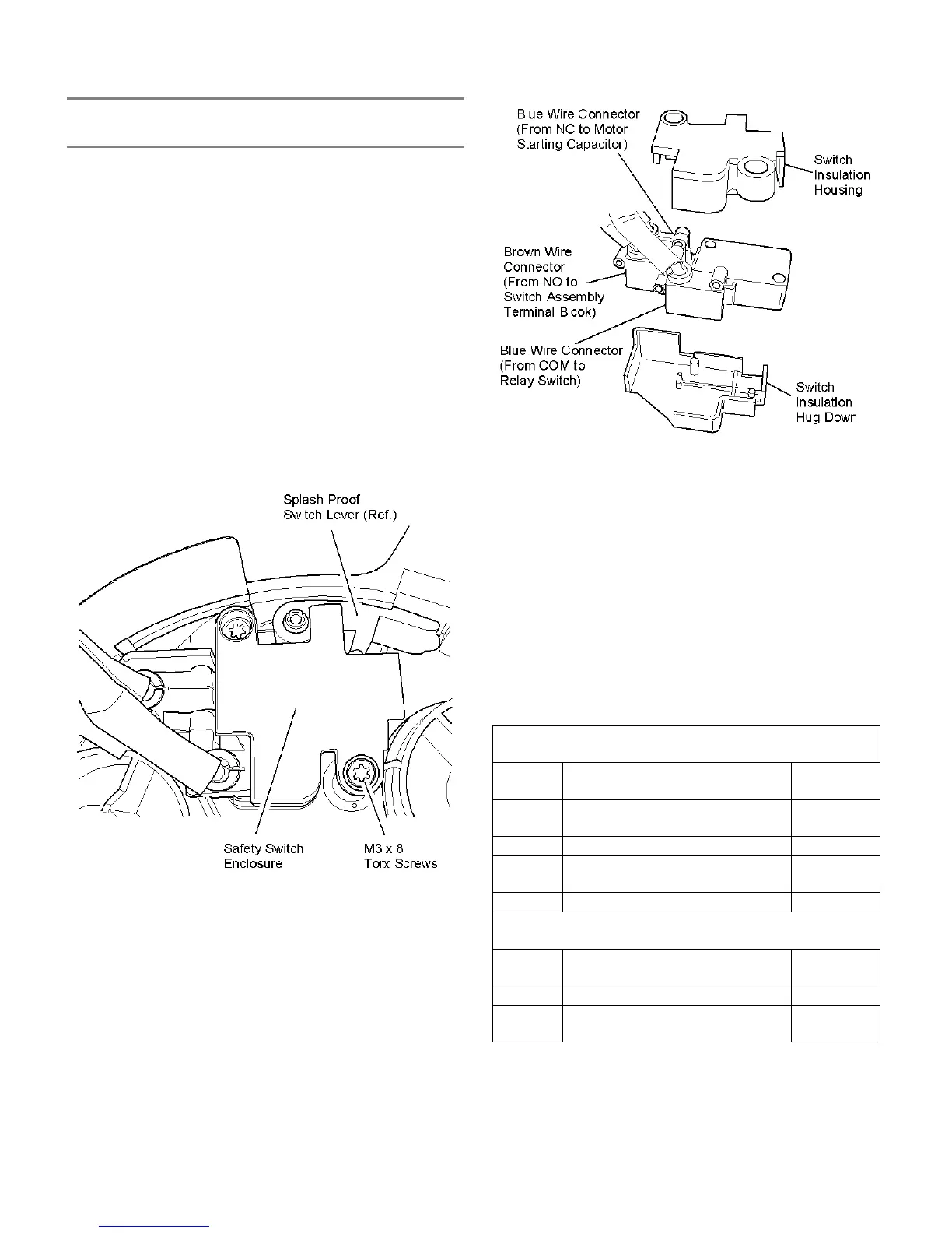
NOTE: The safety switch enclosure consists of
two (2) pieces; a switch insulation housing
and a switch insulation hug down.
5. Remove the safety switch/safety switch enclosure from its
nest in the motor housing.
6. Remove the switch insulation housing and then pull the
safety switch out of the switch insulation hug down.
7. Unplug the three (3) wires/connectors from the safety
switch identified as follows: (Refer to the electrical
schematics for the model type being repaired.)
A. One (1) blue wire from NC on the switch to the
terminal on motor starting capacitor.
B. One (1) blue wire from COM on the switch to the
terminal on the relay switch.
C. One (1) brown wire from NO on the switch to the
switch assembly terminal block.
8. Plug in the three (3) wires and replace the safety
switch/safety switch enclosure in the reverse order.
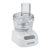
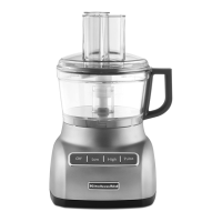
7 CUP FOOD PROCESSOR
SAFETY SWITCH WIRING
WIRE
COLOR
FROM SAFETY SWITCH / TO: LENGTH
from NC terminal to motor starting
capacitor
Blue 250 mm
Blue from COM terminal to relay switch 180 mm
from NO terminal to switch
assembly terminal block
Brown 170 mm
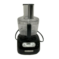
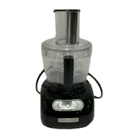
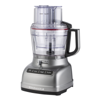
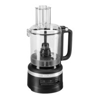
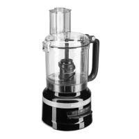
9 & 12 CUP FOOD PROCESSOR
SAFETY SWITCH WIRING
from NC terminal to motor starting
capacitor
Blue 240 mm
Blue from COM terminal to relay switch 220 mm
from NO terminal to switch
assembly terminal block
Brown 165 mm
19