3-8
n
Built-In Single and Double Wall Oven
ELECTRONIC CONTROL DIAGNOSTIC MODE AND COMPONENT TESTING
FOR SERVICE TECHNICIAN’S USE ONLY
11
Component Testing Chart - Oven
To properly check for voltage, complete the following steps:
1. Unplug oven or disconnect power.
2. Connect voltage measurement equipment to check
points.
3. Plug in oven or reconnect power and confirm voltage
reading.
4. Unplug oven or disconnect power.
*NOTEs:
■ Disconnect the harness from the board before performing measurements.
■ See the following table for connector pin identification.
Modes
Relay Logic Bake Broil Conv
Ring
Conv
Fan
Bake (Non-Convect cavity) C C NA NA
Bake (Convect cavity) C C C C
Broil - O - -
Bread Proof C C - -
Convect Bake C C C C
Convect Broil - O - C
Convect Roast C C C C
Self-Clean C C - -
LEGEND
Relay Off Relay Cycles Relay On Not Available
- C O NA
Component Serviceable Side Check Points
Copernicus
Results-Resistance Results-Voltage
Lights Front P5-2 to N (J8-2) 0Ω to 40Ω 120 VAC
Latch Switch Front P3-7 to P3-5 Open circuit
Door Switch Front P3-6 to P3-5 Closed circuit with
oven door closed
Latch Motor Front P5-1 to N (J8-2) 500Ω to 3000Ω 120 VAC motor running
Oven Temperature
Sensor
Front P3-1 to P3-2 1075Ω at 68°F
(20°C) DLB
Meat Probe Side P3-3 to P3-4 9876Ω to 10075Ω
Blower Motor -
High Speed
Rear P5-5 to N (P7-1) 15Ω to 23Ω 120 VAC motor running
Blower Motor -
Low Speed
Rear P5-4 to N (J8-2) 15Ω to 23Ω 120 VAC motor running
Thermal Limiter Rear PX3-1 to L2 (Main line) Closed circuit 0V closed, N/A open
Thermal Fuse (only
for single/double)
Front J8-1 to L1 (P5-7) Closed circuit 0V closed, N/A open
Convection Fan* Rear P5-3 to N (J8-2) 20Ω to 28Ω 120 VAC motor running
Convection
Element*
Front PX1-3 to PX3-2 16.63Ω to 18.38Ω 240 VAC Convection cycle
operating
Bake Element Rear PX1-1 to PX3-2 19.0Ω to 21.6Ω 240 VAC Bake cycle operating
Broil Element Front PX4-2 to PX3-2 13.5Ω to 14.92Ω 240 VAC Broil cycle operating
User Interface
Board
Front P1-4 to P1-3 N/A 14 VDC
Copernicus
Appliance
Manager
Top (single/double)
Side (combo)
P1-2 to P1-5 N/A 14 VDC
Relay Logic Chart
The chart below provides informaon about how the relays react in any cooking mode. The Legend at
the boom of the chart shows what each symbol means. During each of the convecon modes the
convecon fan and convecon element cycle on and o to maintain proper heat - no big surprise
there. The normal BAKE mode also uses the convecon fan and element to get heat build up faster in
PREHEAT and help maintain temperatures during the cycle. The convecon fan can be seen working
during the cooking mode and raises quesons by consumers. The chart conrms that the convecon
fan and element do cycle during the normal cycles too. Remember that the fan will cycle OFF
whenever the oven door is opened. This chart is available in the Tech Sheet that is provided with every
oven Kitchen Aid produces.
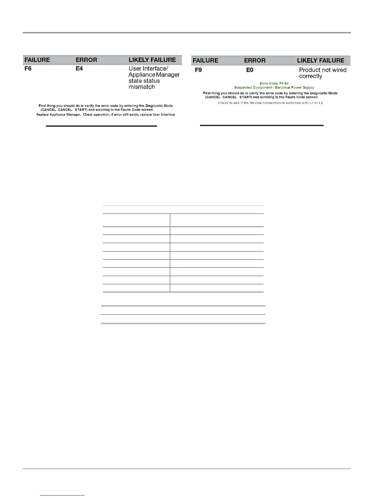
ƌƌŽƌŽĚĞ&ϲϰ
^ƵƐƉĞĐƚĞĚŽŵƉŽŶĞŶƚʹƉƉůŝĂŶĐĞDĂŶĂŐĞƌ
Failure/Error Codes