Do you have a question about the KitchenAid KUIS155H and is the answer not in the manual?
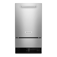
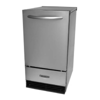
| Type | Under Counter Ice Maker |
|---|---|
| Power | 115V |
| Finish | Stainless Steel |
| Refrigerant | R134a |
| Height | 34.5 inches |
| Ice Shape | Cube |
Essential safety precautions and warnings for operating the ice maker.
Explains model and serial number formats for units manufactured before 2003.
Details model and serial number conventions for units manufactured from 2003 onwards.
Locates the model and serial number identification label on the appliance.
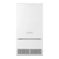
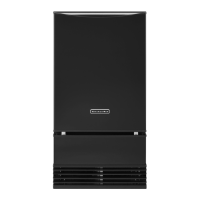
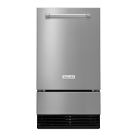
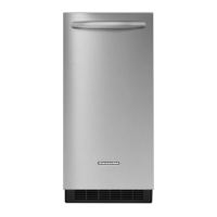
Provides detailed technical specifications for the ice maker model.
Outlines the warranty coverage and terms for KitchenAid ice makers.
Details the necessary electrical power supply and proper grounding requirements.
Details the necessary electrical power supply and grounding requirements.
Instructions for connecting water supply and drain lines to the ice maker.
Instructions for properly connecting the ice maker's drain system.
Overview of the main operating systems within the ice maker.
Description of the different operational cycles the ice maker goes through.
Details the refrigeration system components and their operation, including R134a refrigerant.
Explains the function of the water system, including recirculation and cleaning.
Illustrates the ice maker's electrical system, including power distribution and controls.
Describes the process and conditions of the ice making cycle.
Explains the harvest cycle operation, including electrical, refrigeration, and water systems.
Details the electrical and water system operations during diagnostics and clean cycles.
Details the sequence and duration of the 5-minute Flush Mode.
Describes the Idle Mode, its duration, and the role of the bin thermistor.
Details the minimum and maximum duration of the Freeze Mode.
Explains the Harvest Mode duration and dependencies on the evaporator thermistor.
Information regarding the new control board model #6100499 and its improvements.
Details the operation and features of ice maker models with internal drain pumps.
Illustrates the physical locations of various internal components of the ice maker.
Step-by-step guide to removing specific components like thermistors and water distributor.
Procedure for accessing and removing components housed within the electronic control unit.
Detailed steps for removing the water recirculation pump assembly.
Instructions on how to remove the condenser fan motor.
Procedure for removing the evaporator unit from the ice maker.
Step-by-step guide for removing the water inlet valve.
Instructions for removing the hot gas valve and its solenoid.
Procedure for safely removing the condenser unit.
Step-by-step guide for removing the compressor.
Instructions for removing the internal drain pump on applicable models.
Guide for removing the door and gasket on 15-inch ice maker models.
Guide for removing the door and gasket on 18-inch ice maker models.
Procedure and expected readings for testing the bin thermistor.
Procedure and expected readings for testing the evaporator thermistor.
Instructions for testing the cutter grid component.
Procedure for testing the cutter grid transformer.
Steps to test the water recirculation pump.
Procedure for testing the condenser fan motor.
Testing procedure for the water inlet valve solenoid.
Procedure to test the hot gas valve solenoid.
Testing procedures for the compressor, overload protector, and relay.
How to test the pushbutton switch assembly.
Explains how water quality impacts ice production and quality.
Details the effects of various ingredients on ice quality.
Details the effects of water impurities on the ice maker's performance.
A chart listing common problems, their probable causes, and testing actions.
Flow chart for diagnosing issues with the #6100499 control board.
Provides an overview of the diagnostic flow chart for the control board.
Schematic diagram illustrating the ice maker's electrical wiring.
Diagrams showing simplified electrical strip circuits for different modes.
Strip circuit diagram for the ice making operational mode.
Strip circuit diagram for the harvest operational mode.
General advice and recommendations for cleaning the ice maker.
Step-by-step guide for cleaning the evaporator plate.
Instructions for adjusting the ice thickness setting.
Details the 50-minute Clean Mode, including component cycling and LED status.