0-10 V
4-20 mA
333231302928272625242322212019
18
1715 161413S3S2S1NL1
PE WPE VUPEPENL1´NL1´NL1
7
12 3 45 6
8 9 10 11 12
L1 L1 N N U V W PEPE
N PEPEU V W
1413 15 16 17 18
MR
34 35 36 37 38 39 40 41
a b c de f g h
MZ
1
MZ
2
PE U V W PE PE
MZ
2
13 14 15 16
1
2
4
17 18 PE
∆P
D1
2
3
M3~
NN PE PE
MR
1
2
4
MR
min 4 x 1,5
MZ
1
PEN
MZ
1
MZ
2
1
2
4
181716151413PEPEN393635PEWVU
1
∆P
3
D2
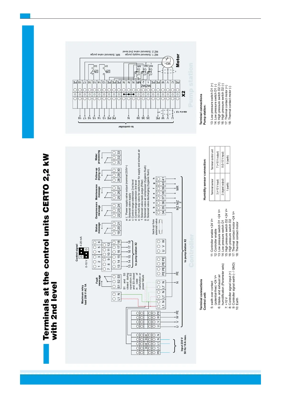
Terminals at the control units CERTO 2,2 kW
with 2nd level
Maximum relay
load 250 V AC 1A
Control signal
Overpressure
message
Status
message
Follow-up
drying run
Water
processing
Fault
message
S1 and S3
closed during
operation.S2
and S3 closed
in case of
malfunction or
power failure
Maintenance
message
Input 230 V
50 Hz 16 A max.
to pump station X2
Controller
to pump station X2
Motor
Pump station
min 4 x 1,5
X2
MZ 1: Solenoid supply purge MR: Solenoid valve purge
MZ 2: Solenoid valve 2nd level
to controller
a: L´ Power supply valve output (nominal 230V~)
b: Solenoid valve supply
c: Control-range extension 2nd level
d: Control-range extension 3rd level
e: 3/2 multi way valve for switchover for supply and exhaust air
f: Solenoid valve back purge (Filter)
g: Solenoid valve air compressor (hygienic ush)
h: Solenoid valve discharging (hygienic ush)
Terminal connections
Pump station:
13: Low pressure switch D1 (+)
14: Low pressure switch D1 (-)
15: High pressure switch D2 (+)
16: High pressure switch D2 (-)
17: Thermal contact motor (+)
18: Thermal contact motor (-)
Humidity sensor connection:
Terminal connections
Control unit:
5: swith over contact
(potential-free) +24 V=
6: Intake- and exhaust air
humidication (Parameter sets)
7: +10 V
8: Controller signal input (+)
9: Controller signal earth (- / GND)
10: Earth
11: Controller enable +24 V=
12: Controller enable
13: Low pressure switch D1 +24 V=
14: Low pressure switch D1
15: High pressure switch D2 +24 V=
16: High pressure switch D2
17: Thermal contact motor +24 V=
18: Thermal contact motor
Terminal sensor Terminal control unit
3 (+10 V input) 7 (+10 V output)
2 (signal output) 8 (0-10 V input)
1 (earth) 9 (earth)
back-up fuse
solenoid valve
 Loading...