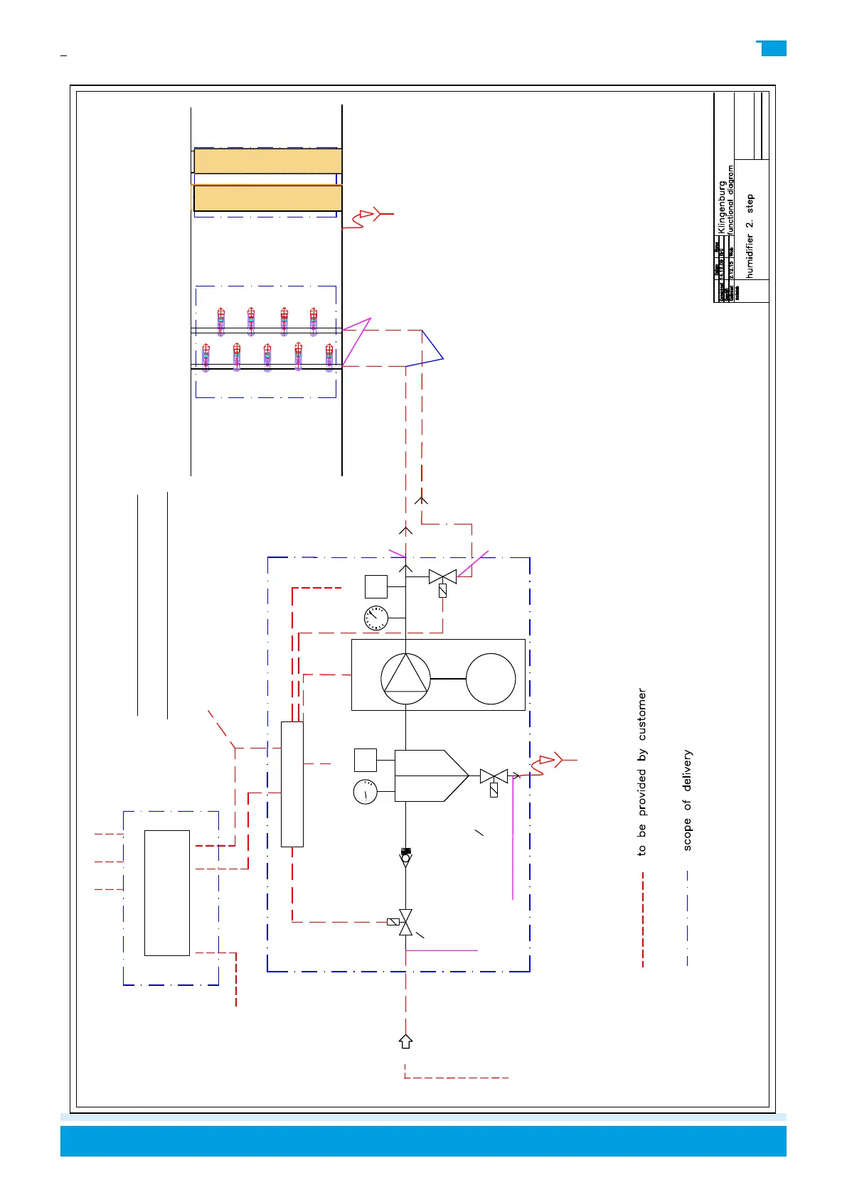
nozzle
arrangement
Filter
2
2
way
solenoid
valve
non return
valve
M
motor
water
supply
pump
pressure
gauge D1
PS
1,6 bar
pressure
gauge D2
PS
150 bar
controler
power supply
according to
documentation
from page 26.
agglomerator & drop
eliminator
High-pressure hoses
included with 3 m in
delivery
Special lengths on
request.
low pressure pipe in
scope of delivery
supply flow
pressure
min. 2 bar
max 5 bar
- provision of voltage supply
- electrical connections between controller and pump station conform to
the wiring diagram
-connection of water pipework between output-osmosis system and input
water supply of pump station with delivered 3m long low pressure hose
-high pressure connections between pump station output and supply water
connections of the humidifier with 3m long high pressure hose
- wiring connections of control signal inputs to humidifier controller
control signal inputs
according to documentation
from page 26.
osmosis
system
2
2
way
solenoid
valve
Functional diagramm high
pressure humidifier 2. step
high
pressure
solenoid
valve 2.
step
connection with
13mm hose fitting or
½“ inside thread
water
stripping
electrical terminal box
pump station
CPU
Electrical connections
according to documentation
from page 26.
Connection via sealing
cone screw connection
10L / M16x1.5
Connection via sealing
cone screw connection
10L / M16x1.5
Connection via
bulkhead fitting
10L / M16x1.5