7/11/2005 VERSION 2.0 20
10. PROFILE CHANGEOVER PROCEDURES
10.1. PROFILE CHANGEOVER GENERAL NOTES
The following descriptions and figures show the machine in the 2x3 A configuration. The process and
required tools are the same for all four configurations.
A changeover can be performed using a set of L-shaped hex wrenches (see Section 4). Sliding the advance
assembly to the back end of the machine can simplify the changeover process. Because the advance
assembly is no longer fully forward, the crimp stops cannot function properly and the knives WILL BE
ABLE to move increasing the risk for injury.
*Insure that the crimp handle is not moved during the changeover process. Failure to do so could
result in serious injury. *
10.1.1. Knives off, Mandrel Assembly Off
Using a 5/16-in hex wrench, remove the three knives before removing the mandrel assembly to reduce the
risk of injury. Remove the three 3/8-in socket head bolts that secure the knives to the machine. Once the
knives are removed, unscrew the 3/8-in socket head bolt that holds the mandrel in place and slide it off the
advance shaft.
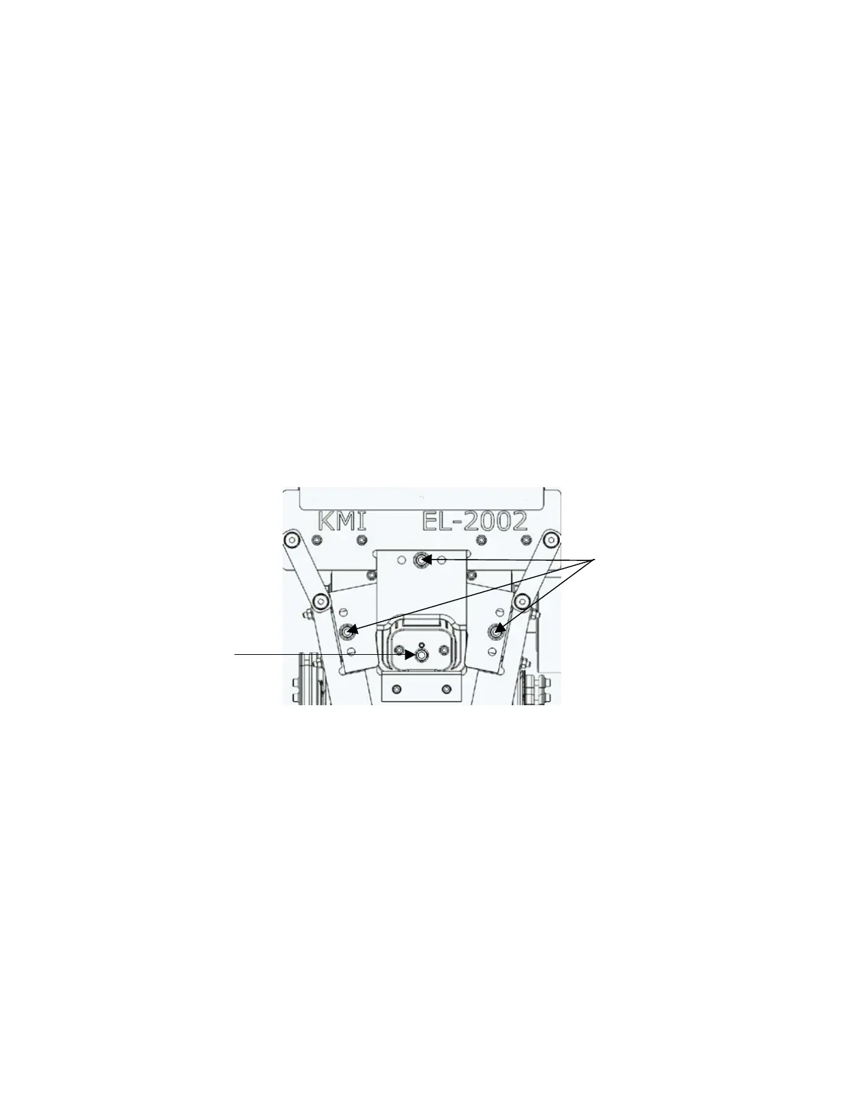
Figure 10-1: Front view of knives and mandrel assembly to be exchanged.
10.1.2. Mandrel Assembly On, Knives On
To mount the new knives and mandrel assembly, use the same four 3/8-in socket head bolts that were used
for the previous set-up. To reduce the risk of serious injury, mount the mandrel assembly first, then the side
knives, and finally, the top knife. Mount the mandrel assembly first. Make sure the heads of the two ¼-20
socket head screws are facing the operator and slide onto roller key extending from the gear rack. It may be
necessary to slide the advance assembly towards the back of the machine in order to lift gear rack slightly.
Once the mandrel is in place, secure with 3/8 x 1.75-in socket head screw. To mount the side knives, make
sure to place the beveled side of the knife towards the machine and secure with socket head bolt. The
mounting screw needs to be snug, but not too tight that the knife cannot slide side-to-side. This slack will
allow the side knives to contour more to the blank during minor adjustment. Figure 10-2 shows the proper
orientation for the left knife. The right side is also oriented in this fashion.
This 3/8-in
socket head
bolt removes
the mandrel
assembly
These three
3/8-in socket
head bolts
remove the
knives