8
ASSEMBLY INSTRUCTIONS
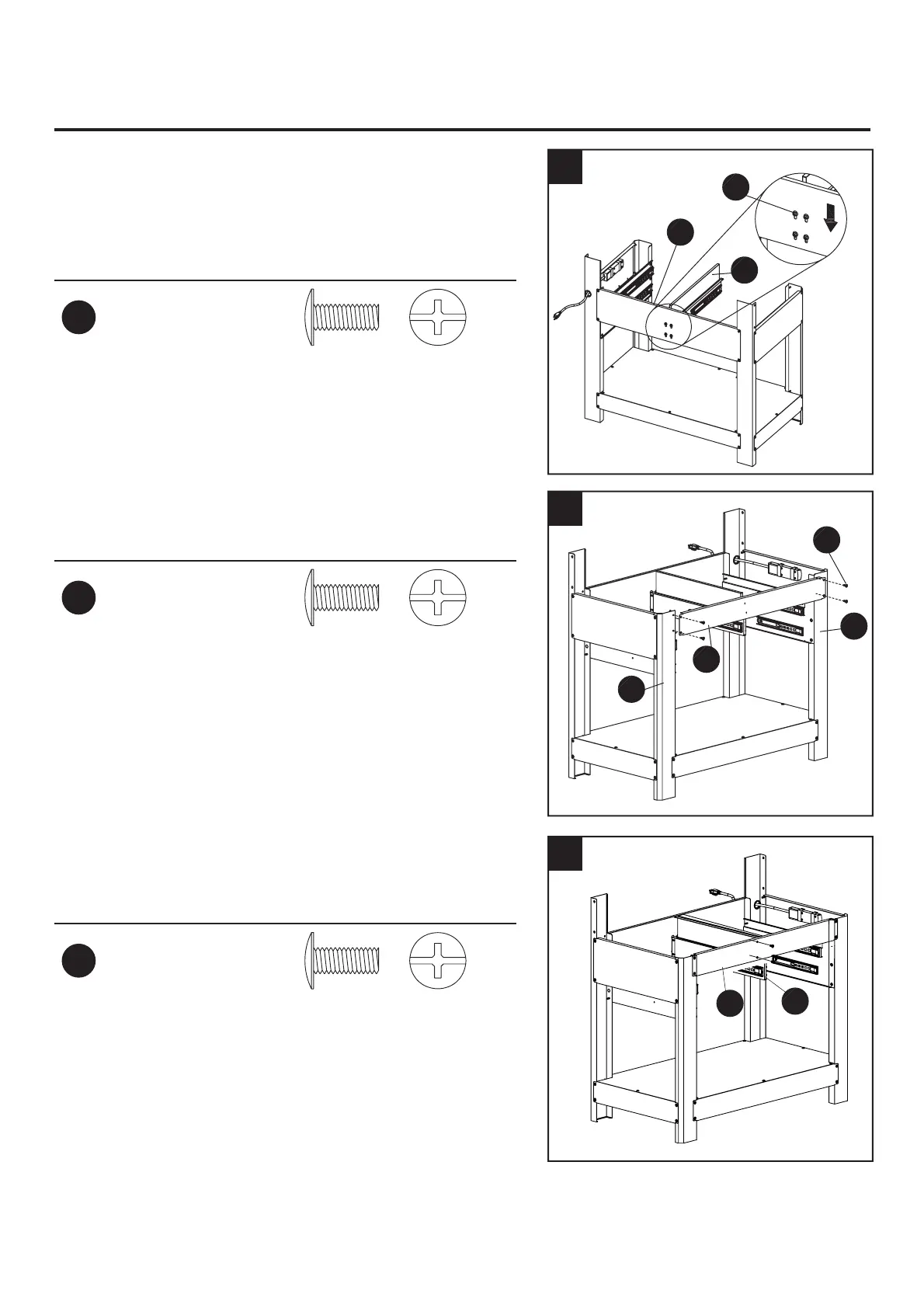
9. Loosely attach screws (AA) to the end of the
intermediate slide support (10). Align the screws
(AA) with the holes in the back panel (14), insert the
screws (AA) into the holes and lower the intermediate
slide support (10). Tighten the screws (AA).
Hardware Used
AA
M6x10 mm
Screw
x 4
10. Attach the upper panel (13) to the left front leg (2L)
and right front leg (6R) using screws (AA).
Hardware Used
AA
M6x10 mm
Screw
x 4
11. Secure the intermediate slide support (10) to the
upper panel (13) by inserting screws (AA) through
the slide support (10) and into the upper panel (13).
Hardware Used
AA
M6x10 mm
Screw
x 2
AA
10
14
9
AA
13
6R
2L
10
11
13
10