EasyManuals Logo

Kobalt 3DPCWB2013 User Manual

Kobalt 3DPCWB2013
15 pages
To Next Page IconTo Next Page
To Previous Page IconTo Previous Page
Page #7 background imageLoading...
Page #7 background image
7
ASSEMBLY INSTRUCTIONS
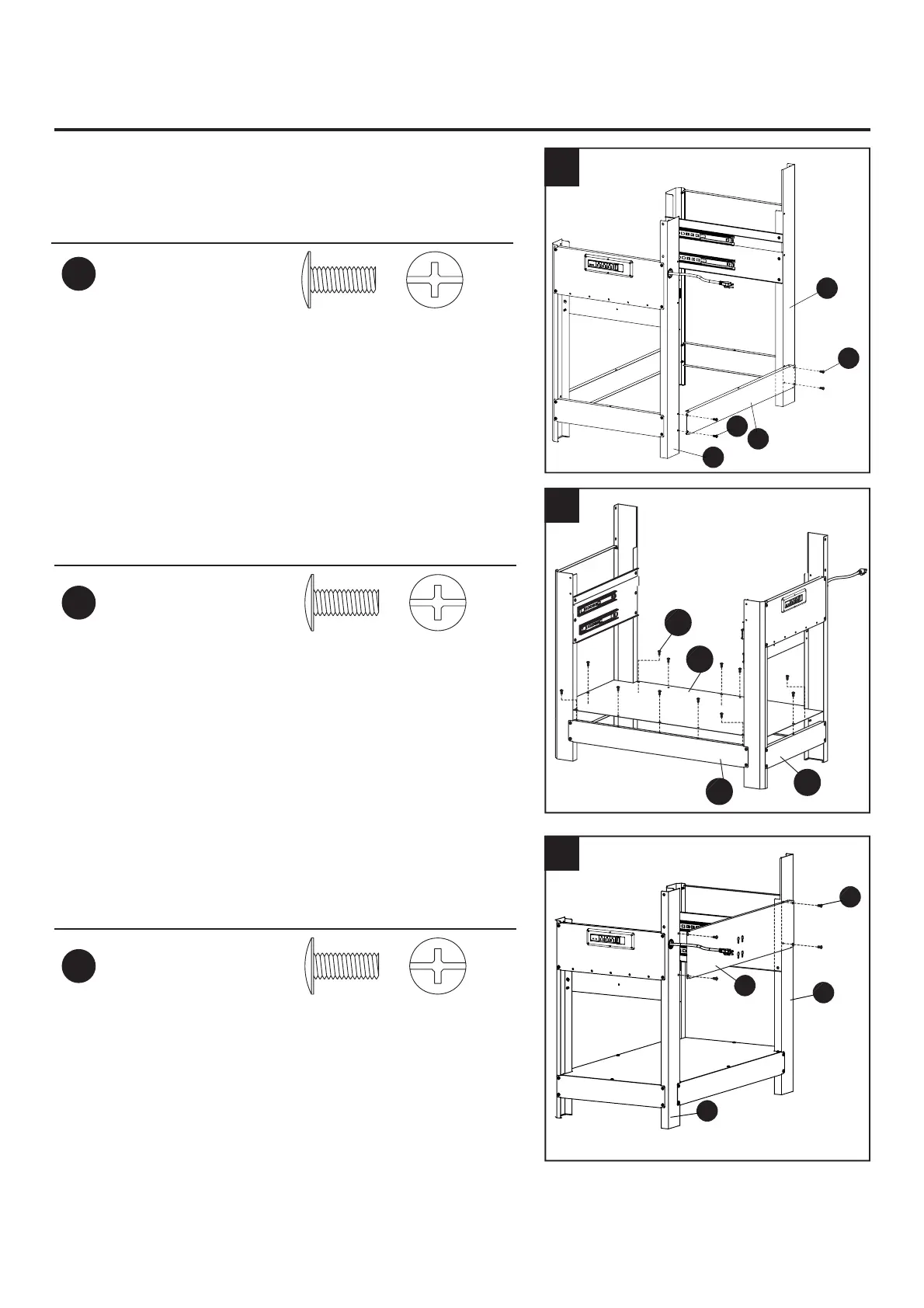
6. Attach a bottom frame (11) to the front of the left and
right rear legs (1L and 5R) using screws (AA). Ensure
the holes on the bottom frame (11) are facing up.
Hardware Used
AA
M6x10 mm
Screw
x 4
7. Attach the base panel (12) to the bottom frames (11)
and side frames (4) using screws (AA).
Hardware Used
AA
M6x10 mm
Screw
x 8
8. Attach the back panel (14) to the left rear leg (1L)
and right rear leg (5R) using screws (AA).
Hardware Used
AA
M6x10 mm
Screw
x 4
1L
11
5R
6
AA
12
11
4
7
AA
14
5R
1L
8
AA
AA

Questions and Answers:

Question and Answer IconNeed help?

Do you have a question about the Kobalt 3DPCWB2013 and is the answer not in the manual?

Kobalt 3DPCWB2013 Specifications

General IconGeneral
BrandKobalt
Model3DPCWB2013
CategoryTool Storage
LanguageEnglish

Related product manuals