Approximate Distance in Feet from Projector to Screen (KODAK Projection Lenses)
Long
110 Slides
Dimension
of
126 Slides 135 Slides
(13
x 17 mm)
Projected
(28
x
28
mm)
(24
x
36
mm) in 2 x 2-inch Mounts
Picture
Curved-field 102
mm
127
mm
102-152
mm
102
mm
127
mm
76
mm
* 102
mm
* 124
mm
*
178
mm
* 100-150
mm
* 76
mm
* 102
mm
* 124
mm
*
Fiat-field
Lens Lens Lens Lens
Zoom
Lens Lens Lens Lens
40"
10 13
'/2
17 23'/2 13'/2 to 20
8
10
'/2
13
50
"
12
'/2
16'1.
21
29 16'/2
to
25 10 13 16'/2
60"
15
20 25 34
'/2
20
to
30 11
'/2
15
'/2
19'/2
70"
17'/2 23
29 40'/2 23
to 34'/2 13'/2 18 22'/2
84"
20
'/2
27'/2
34
'/2
48 27'/2 to 41
'/2
16 21
'/2
27
-These flat-field lenses are recommended for slides mounted in glass. See back cover for list of lenses.
Approximate Dist.ance in Metres from Projector to Screen
Long
Dimension
126 Slides 135 Slides
of
Projected
(26.5 x
26.5
mm)
(22
.9 x 34.2 mm)
Picture
100 em 4.0
to
6.0
125
em
4.9 to 7.4
150 em 5.9
to
8.8
175 em
6.
8 to 10.2
200
em
7.7
to
11.6
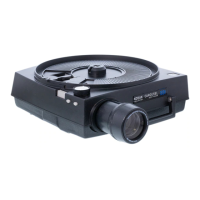
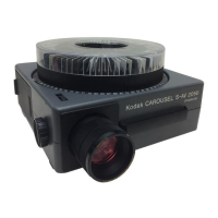
To use
the
zoom lens:
1. In
sta
ll
the
zoom lens by moving
the
focus
knob
toward
the
top
of
the
projector
and guid
in
g
the
l
ens
into
the
projector
. In
sert
the
lens far
enough
into
its
recess so th
at
the
gear
teeth
on
the
lens
barre
l will be
engaged by
the
gear
on
the
focus-
knob
shaft.
2_
Rotate
the
focus
knob
until
the
pro-
jected
image is sharp.
3.
Rotate
the
front
part
of
the
lens bar-
rel
unti
l the image
fi
lls the screen.
4. To
obtain
maximum image
sharp
-
ness
and
the desired image size,
you
may need to
repeat
steps 2
and
3
al
ternate
l
y.
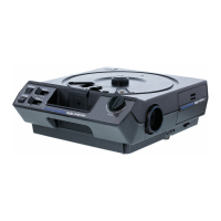
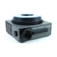
SLIDE TRAY
Furnished
with
some projectors is
the
KODAK
CAROUSEL
'
TRANSVUE
140
Slide Tray. This
tray
is made
of
a
translucent
material
whieh allows you
to see
the
slide-identification
numbers
on the
tray
without tu
rning
on
the
roomlights.
It
ho
lds
140
slides in 2 x
2-
inch
cardboard
or
t
hi
n plastic
mounts
(not glass
or
m
eta
l mounts)
up
to 1/
16-
inch thick. Since this
tray
was
de-
signed to hold as many slides as possi-
ble,
the
slide
compartments
in
the
tray
are qu
ite
narrow.
For
this reason,
your
slide mo
un
ts should be in good condi-
tion. Mo
un
ts which
are
warped
or
bent
may fail to drop from
the
tray
into
the
projector.
If
this happens,
stra
igh
te
n
the
mount
with
your fingers
or
place
3
.1
to
4.7
3.9
to
5.8
4.6
to
6.9
5.3
to
8.0
6.0
to
9.1
the
slide
in
a new mount, su
ch
as a
KODAK
READY-MOUNT.
Slides may n
ot
drop
if
the
front
of
the
projector
is
ra
i
sed
too
h
ig
h.
See
"E
l
evatio
n
,"
page
8.
Clip
off
all
mount
corners that are
frayed. Do not attempt to project slides
mounted
with
loose or sticky tape.
As
the
slide
tray
revolves,
the
nu
m-
ber
of
the s
li
de being projected wi
ll
be
opposite
the
gate
index on the projec-
tor.
You
can
obtain
additiona
l
slide
trays
fro
m
yo
ur
dea
l
er;
see
b
ac
k
cover.
LOCK RING
or Adapters
102-152
mm
102 mm
178
mm*
100-150
mm
* 65
mm
* 76
mm
* 102
mm
*
Lens
Zoom
Lens Lens Lens Lens
18
'/2
10
'/2
to
16 14
16'
/2
22
23
13
to
19
'/2
17 20
'/2
27'/2
27 15
'/2
to
23
'/2
20
'/2
24
'/2
33
31
'/2
18
to
27 24 28
'/2
38
37
'/2
21
'/2
to
32
28
'/2
34
'/2
45
'/2
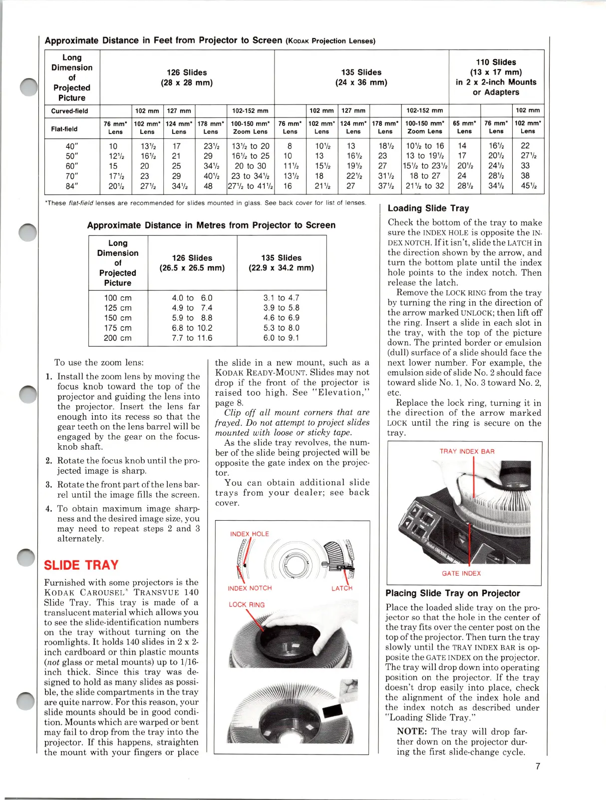
Loading Slide Tray
Check
the
bottom
of
the
tray
to make
sure
the
INDEX
HOLE
is opposite
the
IN·
DEX
NOTCH.
Hit
isn't, slide
th
e
LATC
H in
the
direction
shown by the arrow,
and
turn
the
bottom
plate
u
nti
l the
in
dex
hole points to
the
index
notc
h.
Then
re
lease
the
l
atch
.
Remove
the
LOCK
RING
from
the
tray
by
turning
the
ring
in
the
di
rection
of
the
arrow
marked
UNLOCK;
then
lift off
the
ring
.
Insert
a slide
in
each
sl
ot
in
the
tray
,
with
the
top
of
the
pict
u
re
down.
The
printed
border
or
emul
sion
(dull) surface
of
a slide should face
the
next
lower number.
For
exampl
e,
the
em
ulsion side
of
slide
No.2
should face
toward
slide
No.1,
No. 3
toward
No.2,
etc.
Repl
ace
the
lock ring, tu
rning
it
in
the
direction
of
the
arrow
marked
LOCK
until
the
ring
is
secure
on
the
tray.
TRAY INDEX BAR
GATE INDEX
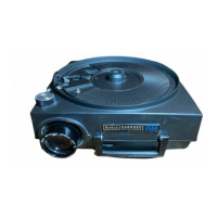
PlaCing Slide Tray on Projector
Place the loaded slide
tray
on the pro-
jector
so
that
the hole in the
center
of
the
tray
fits over
the
center
post on the
top
of
the projector. Then tu
rn
the
tray
slowly
until
the
TRAY
I
NDEX
BAR
is
op-
posite
the
GATE
INDEX
on
the
projector
.
The
tray
will drop down
into
operating
position on
the
projector.
If
the
tray
doesn't
drop easily
into
place,
check
the
alignment
of
the
index hole and
the
index
notch
as described
under
"Loading Slide
Tray."
N
OTE:
The
tray
will
drop
far-
ther
down on the
projector
dur-
ing
the
first slide-change cycle.
7