35
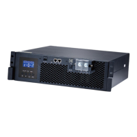
Step 3: Re-connect 2-pin and 14-pin to original position on parallel board as shown below chart.
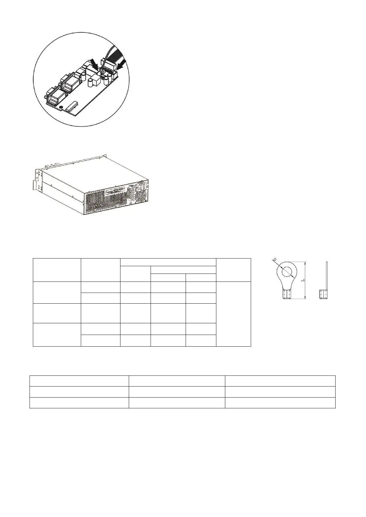
Step 4: Put parallel cover back to the unit. Now the inverter is providing parallel operation function.
4. Wiring Connection
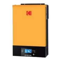
The cable size of each inverter is shown as below:
Recommended battery cable and terminal size for each inverter:
WARNING: Be sure the length of all battery cables is the same. Otherwise, there will be voltage difference
between inverter and battery to cause parallel inverters not working.
Recommended AC input and output cable size for each inverter:
OG-Plus 3.24RM /OG-Plus 3.48RM
CAUTION!! Please make sure the output neutral of each unit is connected together. Otherwise, it
may cause the inverter fail.
You need to connect the cables of each inverter together. Take the battery cables for example: You need to use
a connector or bus-bar as a joint to connect the battery cables together, and then connect to the battery
terminal. The cable size used from joint to battery should be X times cable size in the tables above. “X” indicates
the number of inverters connected in parallel.