36
Regarding AC input and output, please also follow the same principle.
CAUTION!! Please install the breaker at the battery and AC input side. This will ensure the inverter can be
securely disconnected during maintenance and fully protected from over current of battery or AC input. The
recommended mounted location of the breakers is shown in the figures in 5-1 and 5-2.
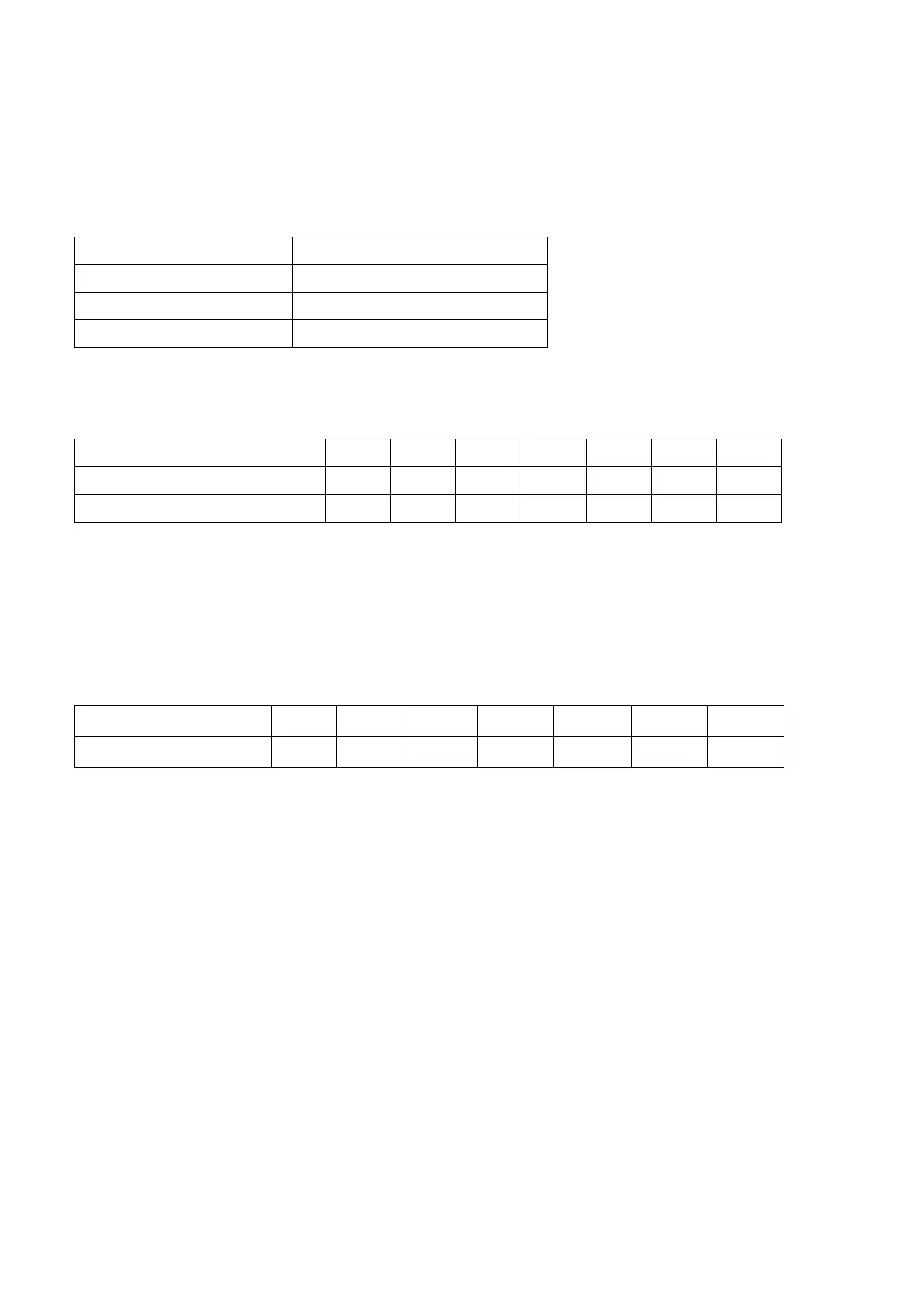
Recommended breaker specification of battery for each inverter:
*If you want to use only one breaker at the battery side for the whole system, the rating of the breaker should
be X times current of 1 unit. “X” indicates the number of inverters connected in parallel.
Recommended breaker specification of AC input:
OG-Plus 3.24RM /OG-Plus 3.48RM
Note1: Also, you can use 40A breaker for OG-Plus 3.24RM/OG-Plus 3.48RM model and 50A for OG-Plus
5.48RM for only 1 unit and install one breaker at its AC input in each inverter.
Note2: Regarding three-phase system, you can use 4-pole breaker directly and the rating of the breaker
should be compatible with the phase current limitation from the phase with maximum units
Recommended battery capacity
Inverter parallel numbers
WARNING! Be sure that all inverters will share the same battery bank. Otherwise, the inverters will transfer to
fault mode.
PV Connection
Please refer to user manual of single unit for PV Connection.
CAUTION: Each inverter should connect to PV modules separately.
 Loading...