14.01 Printed in Japan
Safety
precaution
To ensure proper and safe use of the equipment, please carefully
read and follow the instructions in the Operation Manual.
Tamagawa Office:
2-13-24 Tamagawa, Ota-ku, Tokyo, 146-0095 Japan
Tel: +81-3-3756-6501 Fax: +81-3-3756-6509
Uenohara Office:
5278 Uenohara, Uenohara-shi, Yamanashi, 409-0112 Japan
Tel: +81-554-20-5860 Fax: +81-554-20-5875
• Design and specifications are subject to change without notice.
For details, please contact:
www.koden-electronics.co.jp
overseas@koden-electronics.co.jp
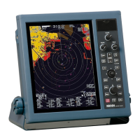
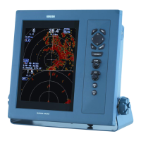
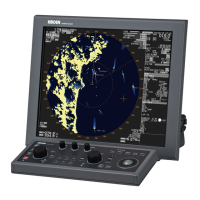
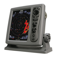
Display unit:
Standard Equipment
RB716A / RB717A / RB718A with RW701A-03 / 04 / 06
RB719A
Antenna-scanner unit:
MRD-101 (MDC-2200 series) MRD-102 (MDC-2500 series)
Weight: 12.5 kg (27.5 lb)
EQUIPMENT LIST
For selecting cable, please contact your nearest distributor
Solid lines: Standard devices and connections
Dashed lines: Optional devices and connections
CONNECTIONS
DIMENSIONS AND WEIGHT
Unit: mm (inch)
Weight: 8.2 kg (18 lb)
Weight:
RB719A
6 feet: 29 kg (64 lb)
9 feett: 33 kg (73 lb)
Weight:
RB716A
3 feet: 21 kg (46 lb)
4 feet: 22 kg (49 lb)
RB717A / 718A
4 feet: 23 kg (51 lb)
6 feet: 25 kg (56 lb)
Weight: 2 kg (4.5 lb)
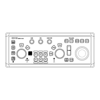
Operation unit:
Antenna- Scanner RB716A 4 kW MDC-2240, 2540 / BB
scanner unit RB717A 6 kW MDC-2260, 2560 / BB
unit RB718A 12 kW MDC-2210, 2510 / BB
RB719A 25 kW MDC-2220, 2520 / BB
Antenna RW701A-03 3 feet MDC-2240, 2540 / BB
unit RW701A-04 4 feet
MDC-2240, 2260, 2210, 2540 / BB, 2560 / BB, 2510 / BB
RW701A-06 6 feet
MDC-2260, 2210, 2520, 2560 / BB, 2510 / BB, 2520 / BB
RW701B-09 9 feet MDC-2220, 2520 / BB
Display unit MRD-101 MDC-2200 series
(Deselect BB type) MRD-102 MDC-2500 series
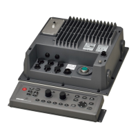
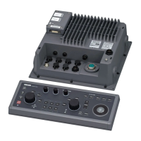
Operation unit MRO-102 MDC-2500 / BB series
Processor unit MRM-102 MDC-2500BB series
Connecting cable 242J159098B-15M 15 m
DC power cable CW-259-2M 2 m
Operation manual, Quick reference, Installation manual, Installation material, Spare parts
AIS interface, Gyro-Log interface, Power rectifier, AC power cable, Water protection RGB cable
Option
Analog RGB output (For external monitor)
Radar signal input / output (For slave display)
NMEA 0183 input / output
AIS signal input
External buzzer output
Display for BB type (Owner supplied)
Power rectifier
PS-010
Operation unit
MRO-102
(For MDC-2500 / BB series)
Optional
cable
100 / 115 VAC
200 / 230 VAC
10.8 to 41.6 VDC
(25 kW: 21.6 to 41.6 VDC)
ATA
AIS interface
AIS-120
Display unit
MRD-101 / 102
Antenna-scanner
unit
BB type
Processor unit
MRM-102
SPECIFICATIONS
320
±
3
(12 19/32)
320
±
3
(12 19/32)
122
±
3
(4 51/64)
102
±
3
(4 1/64)
20
(25/32)
Processor unit:
Weight: 5.1 kg (11.2 lb)
Model MDC-2240 MDC-2260 MDC-2210 MDC-2220
MDC-2540/BB MDC-2560/BB MDC-2510/BB MDC-2520/BB
Ty pe RB716A RB717A RB718A RB719A
Antenna type Open antenna
Antenna length 3 feet 4 feet 4 feet 6 feet 4 feet 6 feet 6 feet 9 feet
Power output (Peak) 4 kW 6 kW 12 kW 25 kW
Output frequency 9410 MHz to 30 MHz
Horizontal beam width 2.5
°
1.8
°
1.8
°
1.2
°
1.8
°
1.2
°
1.8
°
0.8
°
Vertical beam width 22
°
25
°
Rotation 24 rpm or 48 rpm
IF center frequency 60 MHz
Range accuracy 8 meters or 1% of the range scale selected, whichever is the greater
Bearing accuracy 1
°
or less
Minimum detecting distance Within 25 m
Range resolution Within 25 m
Pulse width
0.08 us, 0.25 us, 0.8 us
0.08 us, 0.25 us, 0.5 us, 1 us
0.08 us, 0.3 us, 0.6 us, 1.2 us
Environmental
Operating temperature -25
°
C to +55
°
C
Water Protection IPX6
Model MDC-2240, 2540/BB MDC-2260, 2560/BB MDC-2210, 2510/BB MDC-2220, 2520/BB
Basic Range 0.125 to 48 NM 0.125 to 72 NM 0.125 to 96 NM
Range Scales
Range interval
Presentation modes Head-up, North-up*, Course-up*
Indication system PPI
Video levels 8 levels (colors)
Range unit NM, km,sm
Alarms Echo (IN / OUT), ATA / AIS (CPA / TCPA), Guard zone etc.
Functions
Interference rejection, Target expansion, Zoom, 2 VRM, 2 EBL (true*/ relative), Floating EBL / VRM,
Cursor position (Lat / Lon**), Parallel cursor, Day / Night mode, Bearing (true*/ relative), Trail**, Past course**,
Mark**, Route**, RGB Monitor output, Slave display monitor input / output, External Buzzer output
Input data format and sentences NMEA 0183 Ver.1.5/2.0/3.0
BWC, DBT, DPT, DTM, GGA, GLC, GLL, GNS, HDG, HDM, HDT, MTW, RMA, RMB, RMC, RTE, VBW, VDR, VHW, VTG, WPL, ZDA
Output data format and sentences NMEA 0183 Ver.2.0
HDT, VHW, VTG, GLL, VDR, RSD, OSD, TTM, TLL
NMEA port(s) 3 (input 1, input / output 2)
AIS interface** 200 targets (Option)
ATA** 50 targets
Power supply 10.8 to 41.6 VDC
Power Consumption (at 24VDC)
MDC-2240: 80 W or less MDC-2260: 110 W or less MDC-2210: 130 W or less MDC-2220: 170 W or less
MDC-2540: 100 W or less MDC-2560: 130 W or less MDC-2510: 150 W or less MDC-2520: 200 W or less
MDC-2540BB: 80 W or less MDC-2560BB: 110 W or less MDC-2510BB: 130 W or less MDC-2520BB: 180 W or less
Environmental
Operating temperature -15
°
C to +55
°
C
Water Protection IPX 5 (BB type with optional water protection RGB cable)
* Requires bearing data input.
** Requires bearing data, ship's speed data and latitude / longitude data input.
Model MDC-2240/2260/2210/2220 MDC-2540/2560/2510/2520
MDC-2540BB/2560BB/2510BB/2520BB
Display unit MRD-101 MRD-102 (Deselect BB type)
Display size / type 12.1" color TFT LCD 15" color TFT LCD (Deselect BB type)
Processor unit (BB type only) - MRM-102
Effective diameter 184 mm 228 mm
Display resolution 1024 x 768 pixels (XGA)
Off-centering Max. 66%
Echo area 2 types (Full screen, Inside of effective diameter)
Antenna-scanner unit
Display unit / Processor unit for BB type
MRO-102 (MDC-2500 / BB series) MRM-102 (MDC-2500BB series)
0.125
0.0625
0.125 0.25 0.5
0.25
0.5
0.75
1
1.5
2
3
0.75
4
1
6
1.5
8
2
12
3
16
4
24
6
32
8
48
12
64
16
72
18
96
24
321
±
3
(12 5/8)
364
±
3
(14 21/64)
145
±
3
(5 11/16)
19
(47/64)
31
(1 13/64)
334
±
3
(13 9/64)
321
±
3
(12 5/8)
181
±
3
(7 1/8)
265
±
3
(10 27/64)
385
±
3
(15 11/64)
381
±
3
(14 63/64)
1
7
1
±
3
(6
3
/4
)
5
(1
1
/6
4
)
3
0
(
1
3
/1
6
)
361
±
3
(14 13/64)
385
±
3
(15 5/32)
361
±
3
(14 13/64)
141
±
3
(5 35/64)
57
±
2
(2 1/4)
18.5
(47/64)
31
(1 7/32)
142
±
3
(5 37/64)
64
±
2
(2 17/32)
MAX.450
(17 3/4)
390
±
5
(15 3/8)
220
±
3
(8 11/16)
234
±
3
(9 3/16)
280
±
5
(11)
104
±
5
(4 1/8)
BOW
RW701A-03: 3 feet: 1034
±
5
(40 11/16)
RW701A-04: 4 feet: 1346
±
10
(53)
RW701A-06: 6 feet: 1970
±
10
(77 9/16)
MAX.450
(17 3/4)
470
±
5
(18 1/2)
234
±
3
(9 3/16)
280
±
5
(11)
104
±
5
(4 1/8)
275
±
3
(10 13/16)
BOW
220
±
3
(8 11/16)
RW701A-06: 6 feet: 1970
±
10
(77 9/16)
RW701B-09: 9 feet: 2740
±
10
(107 7/8)