K19404, K19494 Dropping Point Apparatus
Operation and Instruction Manual
K19404, K19494-Manual -9-
4 Setup
Equipment Placement. Make sure the instrument
is placed on a firm, level table in an area with
adequate ventilation or in a hood. The unit may be
leveled by making minor turning adjustments to
the feet located at the base of the unit. Please
note that Koehler does not supply a level with this
equipment.
Environmental Conditions: The instrument
environment must comply with the following
conditions for proper setup:
No / Low Dust
No direct sunlight
Not near heating or AC ventilation ducts
No Vibrations
Clearance from other instruments
Temperature Range: 5 to 40°C
Elevation to 2000 meters
Relative Humidity: < 80%
Ventilation. A fume hood or exhaust system is
required for expending any fumes or vapors that
have been generated while operating the unit.
Flammable vapors and/or steam are generated
during operation and must not be permitted to
accumulate. A canopy-style hood may be used if
the height from the top of the unit to the canopy is
5 feet or less. The exhaust blower should have a
rating of 1000 C.F.M. or greater.
Power. Connect the line cords to properly fused
and grounded receptacles with the correct voltage
as indicated in section 1.3 or on the back of the
unit.
WARNING: For safety, disconnect the
power when performing any maintenance and/or
cleaning..
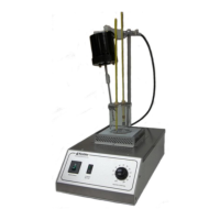
4.1 Assembly Instructions
1. Main Unit Base will come pre-assembled with
the Motor Support Rod affixed to it. At this
time be sure the power switch are in the off
position.
2. Place Beaker (Figure 1, Item 2) on Heating
Plate.
3. Fill the Beaker with the specified heat transfer
fluid to the prescribed level as stated in the
standard test method.
4. Install the Tube and Thermometer Support
(Figure 1, Item 9) to the Beaker positioned
away from the spout of the beaker. This
support can be squeezed for a tighter fit on
the beaker.
5. Insert the bath thermometer into the larger
bath thermometer cork and install into the tube
and thermometer support side without the
metal guide. The bath thermometer should
ultimately be suspended at the same level as
the test tube thermometer when installed.
NOTE: Detail on the Test Tube
Assembly will be described in the Operation
section of the manual.
6. Assemble the stirrer motor (Figure 1, Item 1)
to the motor support rod using the double rod
clamp provided (Figure 1, Item 8).
7. Install the stirrer motor into the beaker and
orientate it so the stirrer motor enters through
the spout of the beaker. Then position the
motor at an angle so that the stirrer will not
interfere with the test tube or bath
thermometer.
8. Plug the stirrer motor line to cord to the
receptacle located at the back of the unit
(Figure 3, Item 11).
4.2 Instrument Descriptions