K19404, K19494 Dropping Point Apparatus
Operation and Instruction Manual
K19404, K19494-Manual -11-
the correct voltage as indicated on the serial
plate on the back of the unit.
13. Level Adjustment Knob: Four adjustment
knobs at each corner of the instrument allow
the user to ensure that the instrument is level
during testing. Please note a wrench or clamp
may be necessary to make proper adjustment.
5 Operation
5.1 Procedure to Fill Test Cup
1. Fill the grease test (Figure 1, Item 3) with
sample by pressing the larger opening into the
grease to be tested until the up is filled.
Remove excess grease with a spatula.
2. Gently press the cup, held in a vertical position
with the smaller opening at the bottom, down
over the polished metal rod (Figure 1, Item 10)
until the latter protrudes about 25mm.
3. Press the rod against the cup in such a manner
that the rod makes contact at both upper and
lower peripheries of the cup.
4. Maintain this contact, rotating the cup on the
rod along the index finger to give a spiral-like
motion down the rod to remove a conical
section of the grease which adheres along the
rod.
5. As the cup approaches the end of the rod,
carefully slip the rod out of the cup so that a
smooth film, free of air bubbles and of
reproducible thickness, remains inside the cup.
6. Refer to Figure 5 below for an illustration of
steps 1 thru 5 above.
Figure 4: Procedure to Fill Test Cup
5.2 Test Tube Apparatus Assembly
1. Place the smaller of the corks with groove
(Figure 1, Item 6) and the cork ring guide
(Figure 1, Item 5) on the thermometer to be
used in the test tube.
2. Place the brass thermometer depth gage
(Figure 1, Item 7) in the test tube.
3. With the thermometer depth gage in position in
the test tube, adjust the position of the upper
cork on the thermometer so that the
thermometer bulb bottoms snugly in the depth
gage.
4. Observe the relative position of the top edge of
the upper cork to the thermometer stem as well
as the relative position of the top edge of the
test tube to the cork.
NOTE: Care must be taken to be certain
that the thermometer is inserted to the same
depth when the apparatus is reassembled with
the grease cup in position.
5. Replace the thermometer depth gage with the
grease test cup (Figure 1, Item 3) so that the
thermometer is inserted to the previously
gaged depth. When properly inserted, the bulb
of the thermometer does not touch either the
grease sample or the cup.
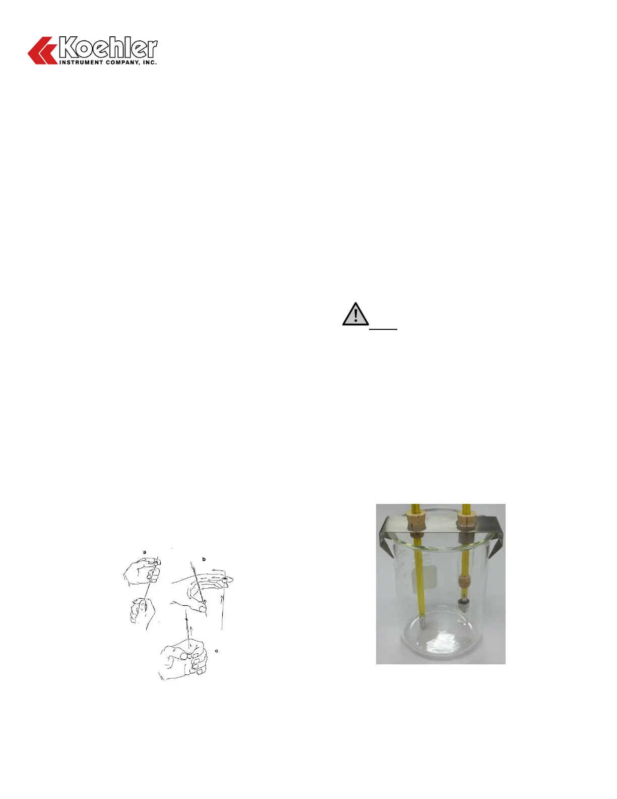
6. Please refer to Figure 2 below for an illustration
of the fully assembled Beaker and Test Tube
Assembly from steps 1 thru 5 above.
Figure 5: Beaker and Test Tube Apparatus Assembly
5.3 Test Procedure