2-10 Operation TP-5631 7/96
Relay Controller Operation
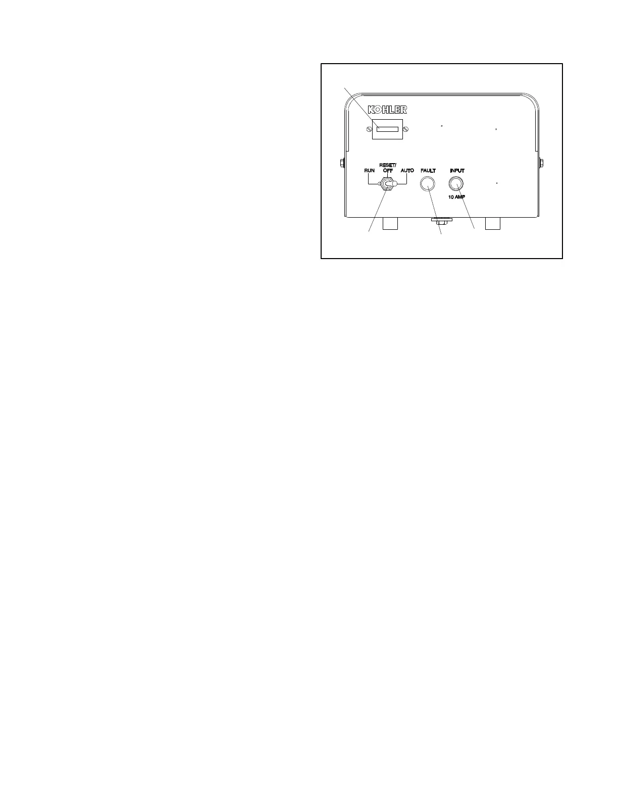
Generator sets equipped with a relay controller refer to
Figure 2-5 and the following descriptions to identify
controller components.
Fault Lamp. Lamp lights to indicate a fault condition.
Generator set shuts down on Overcrank, Overspeed,
and Low Oil Pressure faults. See Fault Shutdowns
following. (Faultlampwillnot staylit aftergenerator set
shuts down. Fault lamp lights as fault occurs.)
Hourmeter. Hourmeter records generator set
operating hours for reference in maintenance
scheduling.
Generator Master Switch (Run/Off-Rest/Auto).
Switch functions as controller reset and generator set
operation switch. Refer to Starting, Stopping, and
Controller Resetting procedure in this section.
Controller Fuse. Fuse (10-amp) protects controller
circuitry.
A-227600
1
2
3
4
1. Hourmeter
2. Controller fuse
3. Fault lamp
4. Generator master switch
5. AC circuit breaker (not shown)
Figure 2-5. Relay Controller Features