TP-6805 8/15 145Section 8 Wiring Diagrams
Section 8 Wiring Diagrams
This section contains wiring diagrams and schematics
for the generator sets. Figure 8-1 lists the drawing
numbers and page numbers.
For RESA, RESAL, and RESB models, note that there
are d ifferent drawings for generator sets equipped with
original and revised controllers. Compare your
controller to the illustrations in Section 4.2 to determine
which controller is installed on the generator set, then
find the applicable drawings in Figure 8-1, below.
All RESC, RESCL, and RESD models are equipped with
revised controllers.
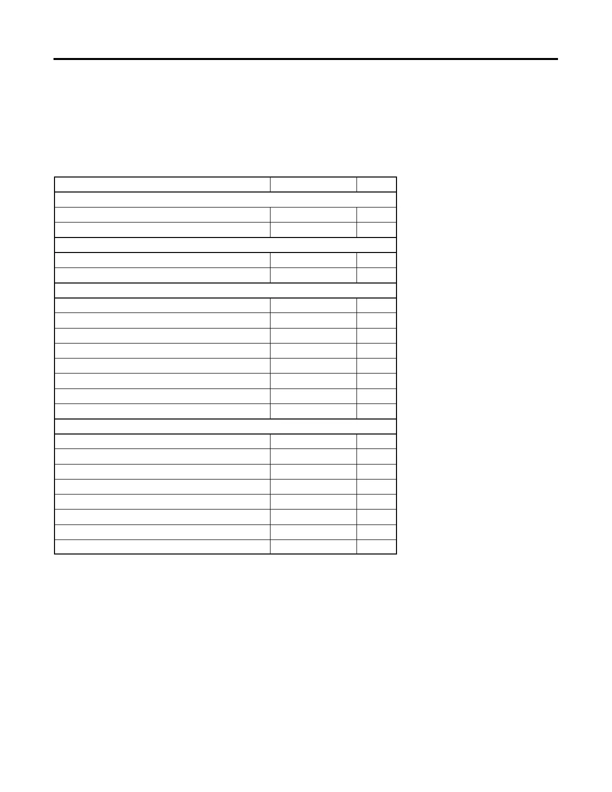
Drawing Description Drawing Number Page
14/20RESA/RESAL with original controller
Schematic Diagram ADV-8164-D 146
Point-to-Point Wiring Diagram GM81217-D 147
20RESB with original controller
Schematic Diagram ADV-8563--A 148
Wiring Diagram GM89939--A 149
14/20RESA/RESAL an d 20RESB with revised controller
Schematic Diagram ADV-8706-C
1 phase, 2 pole circuit breaker Sheet 1 150
1 phase, 1 pole circuit breaker Sheet 2 151
3 phase, 3 pole circuit breaker Sheet 3 152
Wiring Diagram GM93298-C
1 phase, 2 pole circuit breaker Sheet 1 153
1 phase, 1 pole circuit breaker Sheet 2 154
3 phase, 3 pole circuit breaker Sheet 3 155
20RESC/RESCL and 20RESD
Schematic Diagram ADV-8771
1 phase, 2 pole circuit breaker Sheet 1 156
1 phase, 1 pole circuit breaker Sheet 2 157
3 phase, 3 pole circuit breaker Sheet 3 158
Wiring Diagram GM96293
1 phase, 2 pole circuit breaker Sheet 1 159
1 phase, 1 pole circuit breaker Sheet 2 160
3 phase, 3 pole circuit breaker Sheet 3 161
Figure 8-1 Drawings and Diagrams

 Loading...


