TP-6198 3/15 17Section 1 Specifications
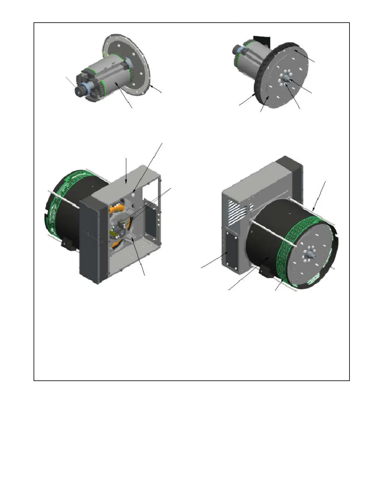
1. Drive disc
2. Rotor assembly
3. Slip rings. See Section 5.5.
4. Apply permabond HM-128
5. Apply anti-seize compound
6. Drive disc (qty. 2)
7. Fan
8. Junction box
9. Overbolts (qty. 4). Upper left overbolt (as viewed from inside
the junction box) requires a lock washer.
10. End bracket assembly
11. Brushes. See Section 5.6.
12. Circuit breaker cover
13. Stator assembly
14. Fan guard
2
GM78230
1
9
8
10
12
13
Note: See Section 1.4 for torque values. See Section 5 for alternator test procedures.
14
9
7
6
5
4
See Note
11
3
Figure 1-3 Alternator Assembly
 Loading...


