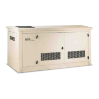
TP-6198 3/1516 Section 1 Specifications
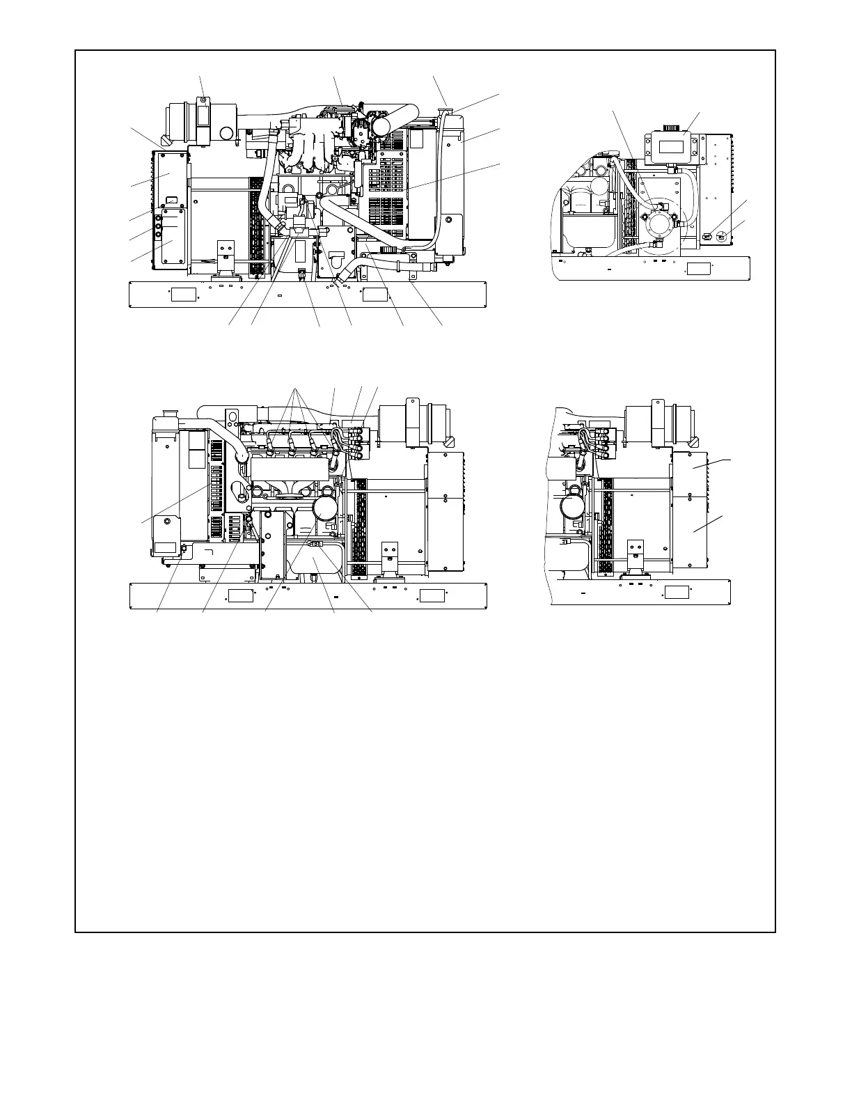
1. Air cleaner
2. ECM and EPR (electronic fuel pressure regulator)
3. Pressure cap (engine coolant fill)
4. Coolant overflow tube
5. Radiator
6. Belt guard
7. Coolant overflow bottle
8. LOP switch location
9. Positive (+) battery connection point
10. Oil drain valve
11. Fuel solenoid valves (two required for UL 2200)
12. Fuel inlet
13. AC circuit breaker panel
14. Generator set fuses
15. Generator set master switch
16. Advanced Digital Control, ADC 2100
17. Nameplate
18. Spark plugs
19. Oil fill (on valve cover)
20. Engine fuses
21. Oil check (dipstick)
22. Remote customer interface connector
23. Customer load lead access
24. Battery cables
25. Battery location (battery not shown)
26. Lube oil filter
27. Negative (--) battery connection point
28. Coolant drain
29. Cooling air inlet
30. Oil makeup assembly with sight gauge (optional, for 30 kW)
31. Oil reservoir
32. Load lead access, behind panel
33. Customer interface connection, behind panel
Oil Makeup Kit
(optional, for 30 kW
only)
10
13
16
1
4
15
7
6
9
5
11
12
14
8
18
29
17
2628
27
30
31
32
2119
2425
20
Units with Customer
Connection Box
33
32
ADV-8159
Note: The enclosure is not shown in these service views.
23
22
Figure 1-2 Generator Set Service View, RESA/REYG Models
 Loading...