TP-6071 3/0040 Section 8 Component Troubleshooting
To further check the generator set components,
disconnect the battery and remove the wiring harness
plugs from the controller circuit board. Use an
ohmmeter to check the continuity of the components
and to isolate inoperative components. Refer to
Figure 8-2 and Figure 8-3.
Note: Before performing ohmmeter checks, disconnect
the generator set battery to prevent damage to
the ohmmeter.
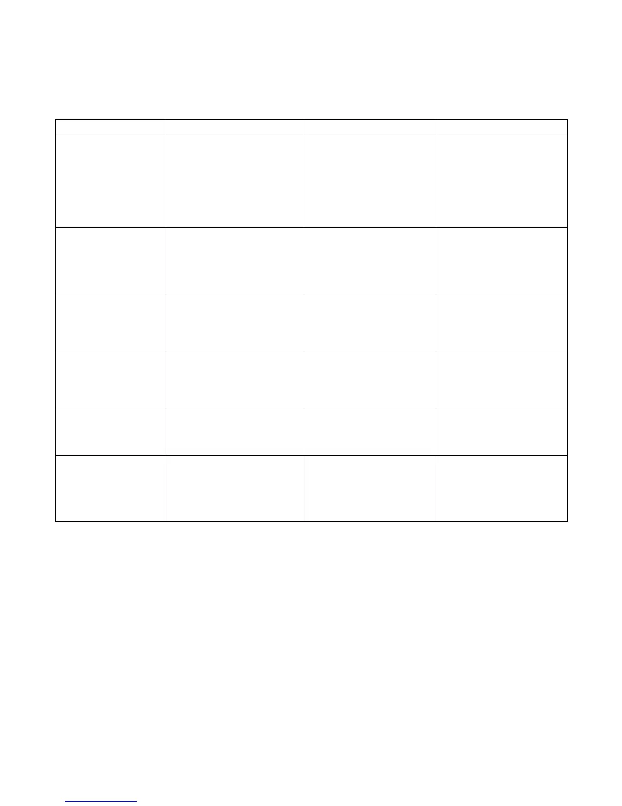
Component Ohmmeter Connections Procedure Results
Start/stop switch Connect the ohmmeter to the P2-6
and P2-4 leads.
Place the ohmmeter on the
R x 1000 scale. Place the rocker
switch in the START position.
If the switch is functional, zero
ohms continuity. Any resistance
other than zero or very low
ohms—replace the switch.
Connect the ohmmeter to the P2-6
and P2-5 leads.
Place the ohmmeter on the
R x 1000 scale. Place the rocker
switch in the STOP position.
If the switch is functional, zero
ohms continuity. Any resistance
other than zero or very low
ohms—replace the switch.
K20 relay coil and wiring Connect the ohmmeter to the P1-4
and P1-9 leads.
Place the ohmmeter on the R x 1
scale.
If functional—85 ohms. Low
resistance—shorted C relay coil
and/or wiring. High
resistance—open C relay and/or
wiring. Replace the controller
board.
Starter solenoid (S relay) Connect the ohmmeter to the P4-22
lead and the battery positive (+)
cable. Note: The J4 and P4 leads
must be disconnected to perform
this test.
Place the ohmmeter on the R x 1
scale.
If functional—approximately
0.5--0.6 ohms at 27_C(80_F).
Controller 10-amp circuit
breaker and wiring
Connect the ohmmeter to the
battery positive (+) cable and the
P1-14 lead.
Note: The J4 and P4 leads must
be connected to perform this test.
Place the ohmmeter on the
R x 1000 scale.
If functional—zero or very low
ohms. No reading (infinity)—
open circuit or circuit breaker
tripped.
Exciter field windings P7 (FP/FN)
Note: Disconnect P7 connector for
this test
Ohmmeter on R x 1 scale.
Disconnect the exciter field leads
to voltage regulator at P6.
If functional—see Section 1,
Specifications. Low
resistance—exciter shorted. High
resistance—exciter open.
Exciter armature windings Disconnect the armature leads from
the rectifier. Connect the ohm
leads. Repeat the test on the third
lead.
Ohmmeter on R x 1 scale If functional—see Section1,
Specifications. Low
resistance—armature windings
shorted. High
resistance—armature windings
open.
Figure 8-2 Engine/Generator Component Testing—Relay Controller (Sheet 2 of 3)