TP-6071 3/00 43Section 9 Generator Disassembly/Reassembly
Section 9 Generator Disassembly/Reassembly
9.1 Disassembly
Disconnect all of the external connections—battery
cables at the battery (negative (--) lead first), AC-output
leads in the controller, remote start panel at the
controller P3 connector, water line at the seawater
pump, fuel line at the fuel pump filter inlet, and exhaust
line at the mixing elbow. Observe all of the safety
precautions listed at the beginning of this manual during
the disassembly/reassembly procedures.
Note: Because this manual covers several models, the
procedure for disassembly may vary because of
product updates and the assembly variations.
Note: The voltage regulator is located in the controller
box. Remove the controller cover to service the
voltage regulator. Adjustments are possible
without removing the voltage regulator from the
controller.
Disassembly Procedure:
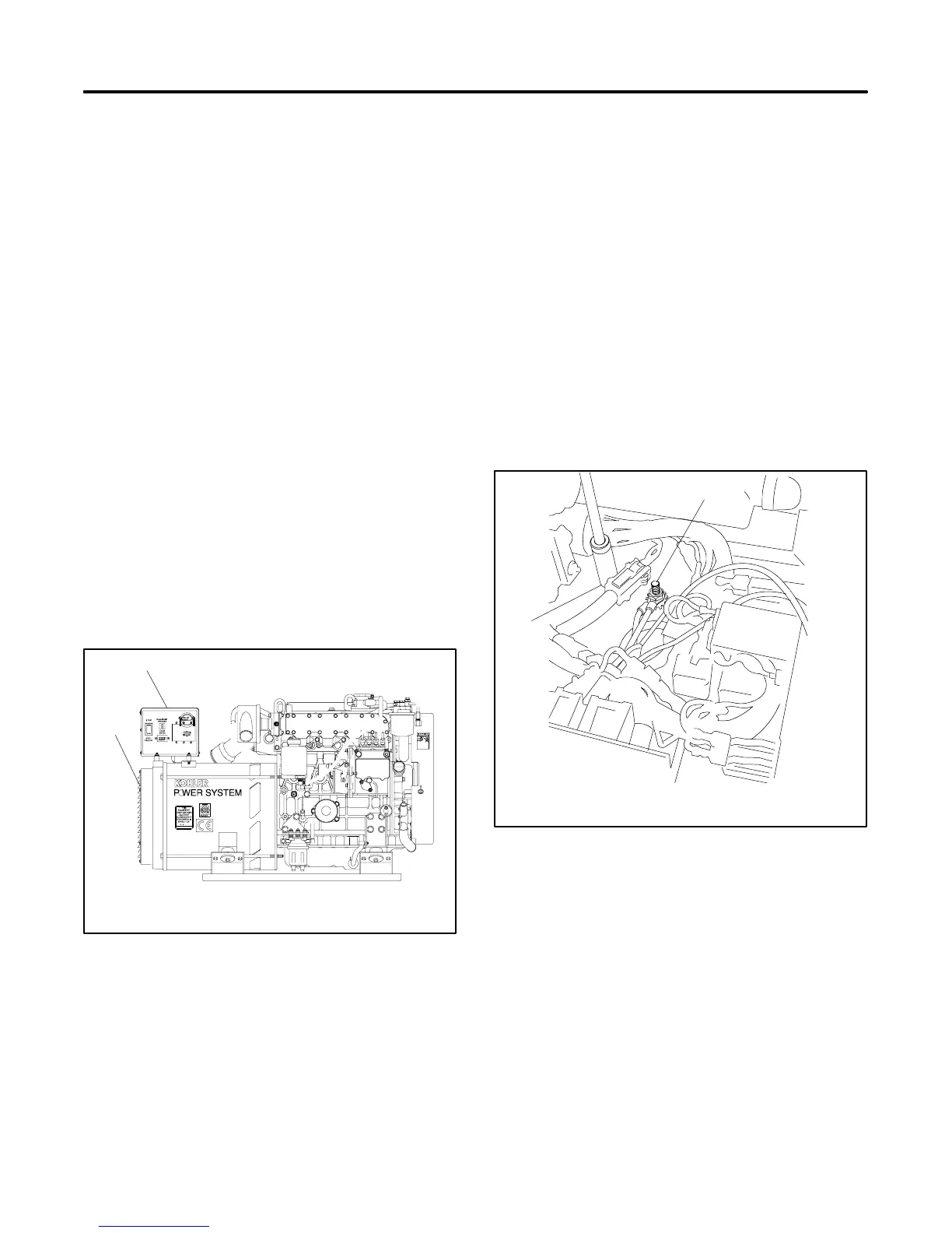
1. Remove the end panel from the alternator end of
the generator set. See Figure 9-1.
2. Loosen the four screws and lift off the controller
cover. See Figure 9-1.
CD-250000-AJ
1
2
1. Controller cover
2. Alternator end panel
Figure 9-1 Covers
3. Disconnect the P4 (22-pin) connector from J4.
4. Remove the ground strap.
Note: It is possible to connect the output leads in
various positions for different voltage
configurations. Mark leads 1, 2, 3, and 4 for
correct reconnection.
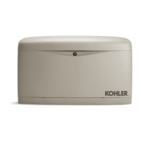
5. Disconnect generator output leads 1, 2, 3, and 4
from the circuit breaker and neutral stud (L0). See
Figure 9-2.
6. Remove the four controller mount locknuts. See
Figure 9-2.
7. Lift the controller from the rubber mounts while
guiding the leads through the bottom hole of the
controller box.
558863
1
2
1. Controller mount locknut
2. Neutral stud (L0)
Figure 9-2 Controller Removal
8. Remove the tie wraps from the wiring harness as
necessary. Disconnect the F1 connectors from the
resistor leads.