TP-6071 3/0044 Section 9 Generator Disassembly/Reassembly
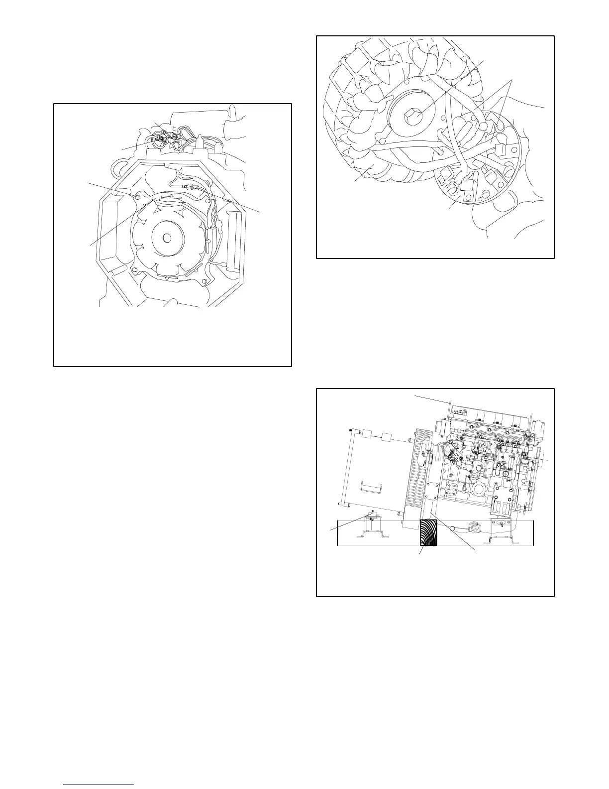
9. Disconnect the P7 (FP and FN) and P6 (F1 and F2)
connectors. See Figure 9-3.
10. Remove the four bolts to remove the exciter field.
SeeFigure9-3.
558864
1
2
3
4
1. P7 connector
2. P6 connector
3. F1 connector
4. Exciter field
5. Bolts (4)
5
Figure 9-3 Exciter Field Removal
11. Remove the three bolts and spacers from the
rectifier board.
12. Disconnect the main field rotor leads from the
rectifier board positive/negative terminals.
Remove the armature retaining bolt and washer.
SeeFigure9-4.
13. Remove the armature from the shaft, guiding the
rotor leads through the armature bores. See
Figure 9-4.
14. Remove the tie wraps and disconnect the P8 (33,
44, 55, B1, and B2) wire connector.
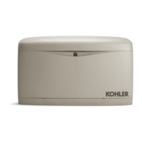
15. Attach a hoist hook to the generator lifting eye. See
Figure 9-5.
Note: The hoist capacity rating should be one-half
ton or greater.
558865
1
2
3
4
1. Armature
2. Armature retaining bolt
3. Rotor leads
4. Rectifier board
Figure 9-4 Armature Removal
16. Remove the two vibromount bolts. See Figure 9-5.
17. Raise the alternator end and place a wood block
under the locator plate. Lower the alternator until
the wood block supports the backplate. See
Figure 9-5.
18. Remove the four overbolts from the end bracket.
558866
1
3
2
4
1. Lifting eye
2. Backplate
3. Wood block
4. Vibromounts
Figure 9-5 Supporting the Generator, Typical