TP-6953 7/19 177Section 10 Alternator Component Testing and Adjustment
1
2
3
4
5
6
7
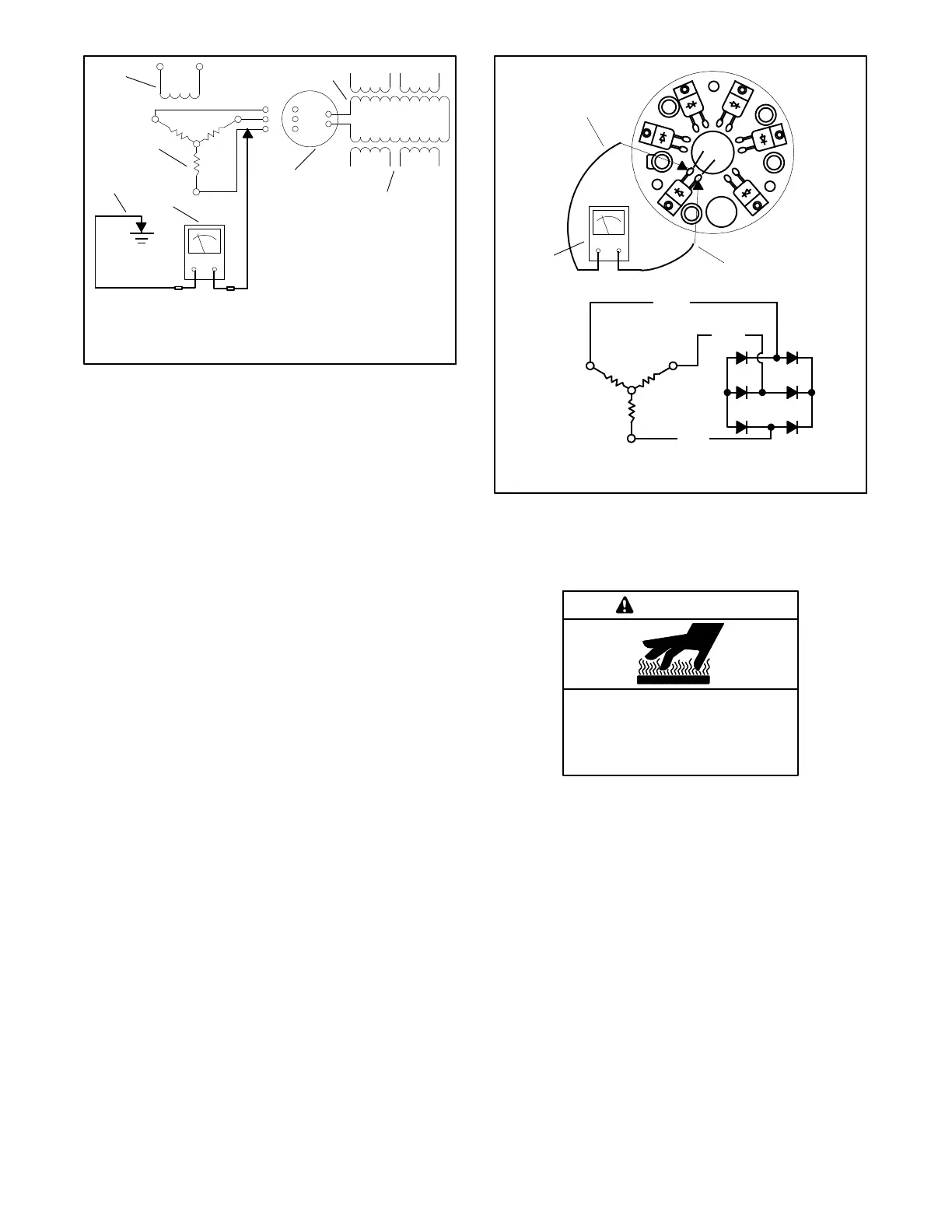
TP-6878-3
1. Main field (rotor)
2. Stator windings
3. Rectifier module
4. Megohmmeter
5. Exciter armature fr ame
(shaft connection)
6. Exciter armature
7. Exciter field winding
F+
F-
AC
AC
AC
M
Figure 10 -6 Megohmmeter Connections on
Exciter Armature
10.3.2 Rectifier Module
The rectifier module located between the exciter
armature and the main field (rotor) converts AC from the
exciter armature to DC, which magnetizes the generator
main field (rotor). Test the rectifier module as described
in the following steps.
Rectifier Module Test Procedure
1. Disconnect the exciter armature and the main field
leads from the rectifier module.
2. Perform a diode check of all six o f the rectifier board
diodes. Replace the rectifier module if any of the
diodes tests differently than described.
a. Test each individual diode using the multimeter
diode check feature if so equipped. Refer to the
multimeter instructions for procedure.
or
b. Use an ohmmeter on the R x 100 scale to check
the resistance of the rectifier diodes as shown
in Figure 10-7. The ohmmeter should s how a
low resistance in one direction and, upon
reversing the ohmmeter leads, a high
resistance in the other direction.
A
B
C
-
+
1
2
TP-6878-3
3
1. Diode terminal
2. Diode terminal
3. Ohmmeter
A1
(AC)
(AC)
(AC)
C1
B1
B
C
+-
Figure 10-7 Rectifier Module Test
10.4 Rotor (Main Field)
Hot engine and exhaust system.
Can cause severe injury or death.
Do not work on the generator set until
it cools.
WARNING
Servicing the alternator. Hot parts can cause severe
injury or death. Avoid touching the alternator field or exciter
armature. When shorted, the alternator field and exciter
armature become hot enough to cause severe burns.
 Loading...


