TP-6953 7/19178 Section 10 Alternator Component Testing and Adjustment
Hazardous voltage.
Can cause severe injury or death.
Operate the generator set only when
all guards and electrical enclosures
areinplace.
Moving parts.
WARNING
High voltage test. Hazardous voltage can cause severe
injury or death. Follow the instructions of the test equipment
manufacturer when performing high-voltage tests on the rotor
or stator. An improper test procedure can damage equipment
or lead to generator set failure.
The generator rotor (magnetized by DC from the rectifier
module) rotating within the stator windings induces AC
in the stator windings. Test the generator rotor (main
field) as described in the following steps. Disassemble
the generator prior to performing this test. See
Section 15, Generator Disassembly/Reassembly.
Generator Main Field (Rotor) Test Procedure
1. With the generator disassembled, disconnect the
generator main field (rotor) windings at the rectifier
module terminals F+ and F- .
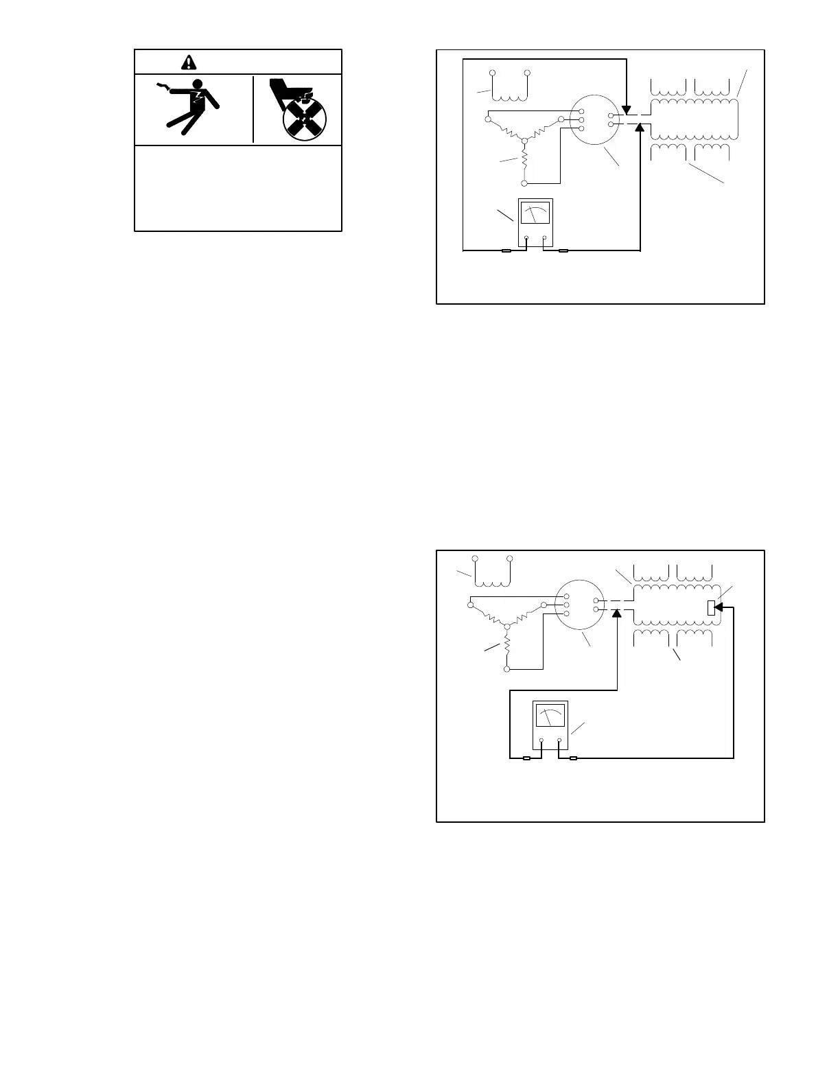
2. Check the main field (rotor) resistance by
connecting an ohmmeter across the main field
(rotor) F+ and F- leads. See Figure 10-8. See
Section 1, Specifications, for the resistance value.
A low reading indicates an internal short and a high
reading indicates an open winding. Repair or
replace the main field (rotor) if the ohmmeter
readings indicate the main field (rotor) is
inoperative. If the resistance test is inconclusive,
perform a megohmmeter test on the main field
(rotor) as described in the next step.
TP-6878-3
1
2
3
5
6
1. Main field (rotor)
2. Stator windings
3. Rectifier module
4. Ohmmeter
5. Exciter armature
6. Exciter field winding
F+
F-
AC
AC
AC
4
Figure 10-8 Ohmmeter Connections on Main Field
3. Check the main field (rotor) for a short-to-ground
condition by using a megohmmeter. Apply
500 volts DC to either field lead (rotor) and the main
field (rotor) frame. Follow the megohmmeter
manufacturer’s instructions for using the
megohmmeter. See Figure 10-9.
A reading of 1.5 MOhms and higher indicates the
main field (rotor) is functional. A reading of less
than 1.5 MOhms indicates deterioration of the
winding insulation and possible current flow to
ground; if so, r eplace the main field (rotor).
TP-6878-3
1
3
4
2
5
6
7
1. Main field (rotor)
2. Main field (rotor) frame
(shaft connection)
3. Stator windings
4. Rectifier module
5. Megohmmeter
6. Exciter armature
7. Exciter field winding
F+
F-
AC
AC
AC
M
Figure 10-9 Megohmmeter Connections on Main
Field
 Loading...


