TP-6953 7/19 181Section 10 Alternator Component Testing and Adjustment
10.6 Voltage Regulator
These generator sets have a controller
(Decision-Makerr 3500) that has an integrated voltage
regulator.
Voltage regulation is performed by the generator set
controller. The activator board only interprets the pulse
width modulator (PWM) signal as a target current for the
alternator field and controls the current to match the
target.
10.7 Activator Board GM88453
10.7.1 General
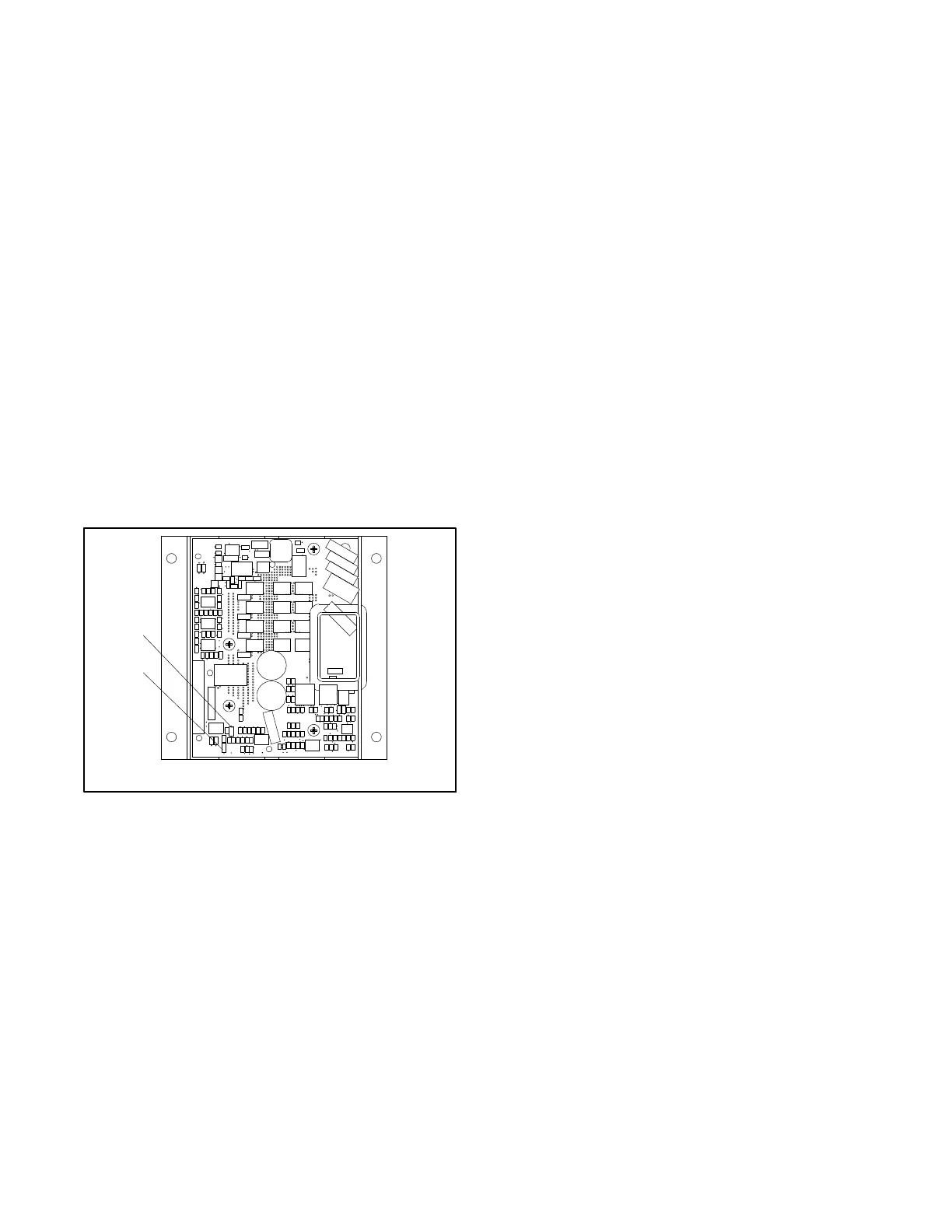
The activator board (Figure 10-16) is a current-
controlling device. The output current of the activator is
controlled to a given target based on the duty cycle of the
pulse width modulated (PWM) signal from the LED
output of the controller. The activator board switches
DC voltage to the field to increase the field current when
the target current increases and turns the field voltage
off until the field current decays to the new level when
the target current decreases.
TP-6878
1. DC Bus LED 1
2. Power LED 2
1
2
Figure 10-16 Activator Board GM88453
The activator board receives power from one of two
sources when used with wound field alternators:
D An auxiliary winding on the alternator. This winding is
located on the stator where it requires field current to
produce voltage. The activator requires an additional
power source to supply initial current to the field
causing the auxiliary winding to produce voltage.
Note: If the generator set has been running recently,
the alternator field will typically have enough
residual magnetism to power the activator
board and provide power to the field.
D The cranking battery provides input voltage without a
second power source to the activator board only
when it is not receiving power from the auxiliary
windings. The activator board energizes a relay that
disconnects the DC input to the activator board when
the AC input reaches about 25 VAC.
The activator board contains two LEDs for
troubleshooting purposes. Power to the activator board
is supplied by the alternator; therefore, the LEDs will
only illuminate while the generator set is running.
D DC Bus. Indicates that the DC bus that provides
power to the field has voltage present. The LED starts
to illuminate at 8 VDC on the bus and is fully
illuminated by about 14 VDC.
D Power. Indicates that activator board is receiving
power and is able to control the output to the field.
This LED m ust be fully illuminated (max. brightness)
before any power is supplied to the field.
10.7.2 Theory of Operation
The activator board receives power as soon as the run
relay is energized (the flash relay is not energized).
After receiving power, the board begins controlling the
field current to the target sent by the controller.
After the controller requests field current, the activator
applies voltage to the field to increase the field current to
the target. The flash relay is energized when the
auxiliary winding voltage reaches about 25 VAC, which
is usually occurs between 800 and 1200 rpm as the
engine accelerates. The field current is limited by the
battery voltage until enough current is flowing on the
rotor field to energize the auxiliary windings.
The a ctivator board controls current to the exciter field
which controls the voltage on the exciter armature that is
rectified by the rotating diode board and provides a DC
voltage to the rotor field. In constant load and speed
operation, the rotor field current is related to the exciter
current.
In transient conditions (changing load or speed)
operation, the two currents may not be related, as the
rotor field has a long time constant (it takes time to
change the rotor field current). The field current in the
main field increases when voltage is applied to it and
decreases when voltage is not applied to it. The voltage
is proportional to the exciter field current. T he voltage
applied to the main field is proportional to the exciter f ield
current.
 Loading...


