TP-6735 7/17 95Section 6 Disassembly/Reassembly
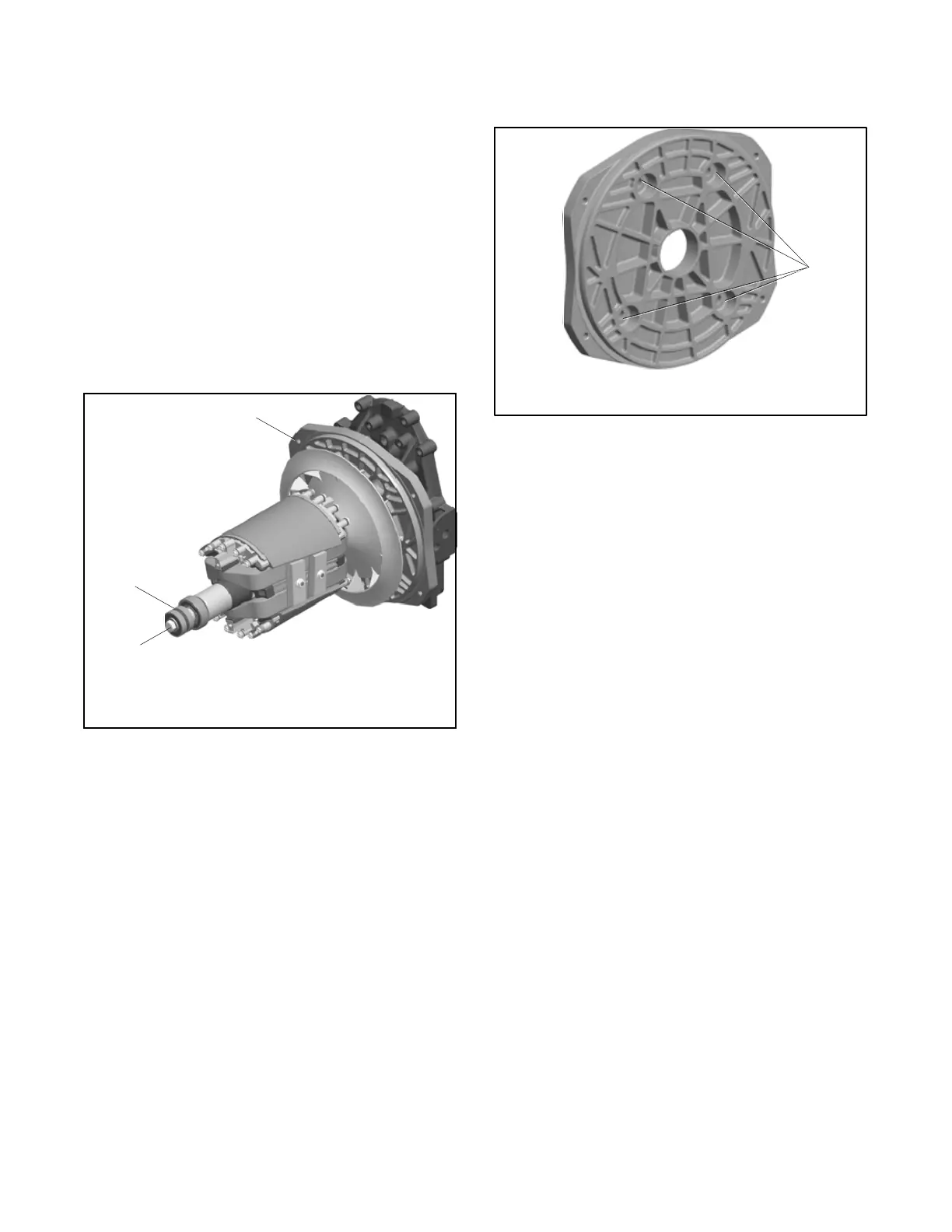
30. Remove the rotor as follows:
a. Loosen but do not remove the rotor thrubolt.
Use a strap wrench on the rotor to keep the
rotor from turning during loosening, if
necessary. See Figure 6-17.
b. Loosen the rotor assembly by striking the side
of the rotor with a soft-faced hammer to loosen
it from the tapered crankshaft fitting. See
Figure 6-17. Rotate the rotor and strike it on
alternate sides until it can be rocked slightly
back and forth.
Note: Do not strike the slip rings.
c. Remove the thrubolt and the rotor. Set the rotor
assembly aside.
GM67344
1
1. Rotor thrubolt
2. Slip rings
3. Generator adaptor (14RES/RESL only)
2
Note: Do not strike the slip
rings when removing
the rotor.
3
Figure 6-17 Rotor Assembly with Thrubolt
31. 14RES/RESL only: Remove the four generator
adapter mounting bolts to remove the generator
adapter, if necessary. See Figure 6-18.
GM60283
1
1. Adapter mounting holes
Figure 6-18 Generator Adapter (14RES/RESL)



 To Next Page