TP-6803 6/1524 Section 1 Installation
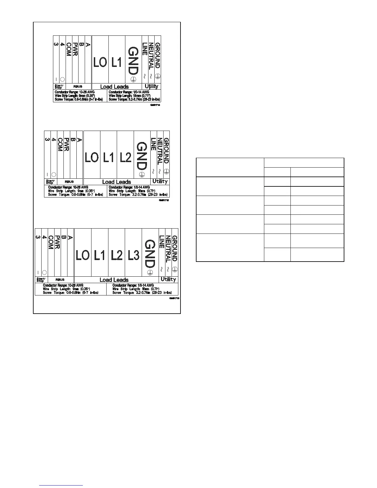
1-Phase, 1-Pole Circuit Breaker
1-Phase, 2-Pole Circuit Breaker
3-Phase
Figure 1-19 Terminal Block Connection Decals
1.9.4 AC Power Supply
The installer must connect AC power for the battery
charger (which is integral to the RDC2 controller) and
the optional accessories shown in Figure 1-20. The
power source must comply with state and local codes.
The power to the battery charger and accessories must
be backed up by the generator so that power is available
at all times.
Be sure to disconnect power at the distribution panel
before making the connections. Connect power leads to
the AC power connection points labeled LINE,
NEUTRAL, and GROUND on the field-connection
terminal block. Connect the circuit to the load side of the
transfer switch so that it is backed up by the generator.
See Figure 1-18 and the wiring diagrams in Section 3 for
connection details.
Equipment
Power Requirement, Max.
Watts Volts at 50/60 Hz
Battery charger
(standard)
50 100--120 VAC
50 200--250 VAC
Carburetor heater
(optional)
37
100--120 VAC
37
200--250 VAC
Battery heater (optional)
50
100--120 VAC
50
200--250 VAC
Fuel regulator heater
(optional; available for
20RESA/RESAL/RESC/
RESCL only)
60 100--120 VAC
100 200--250 VAC
Figure 1-20 Power Requirements
 Loading...


