TP-6803 6/1528 Section 1 Installation
RXT*
3
COM
PWR
B
A
4
PIM
Generator Set
COM
COM
PWR
COM
PWR
PWR
B
A
B
A
B
A
COM
PWR
B
A
COM
PWR
B
A
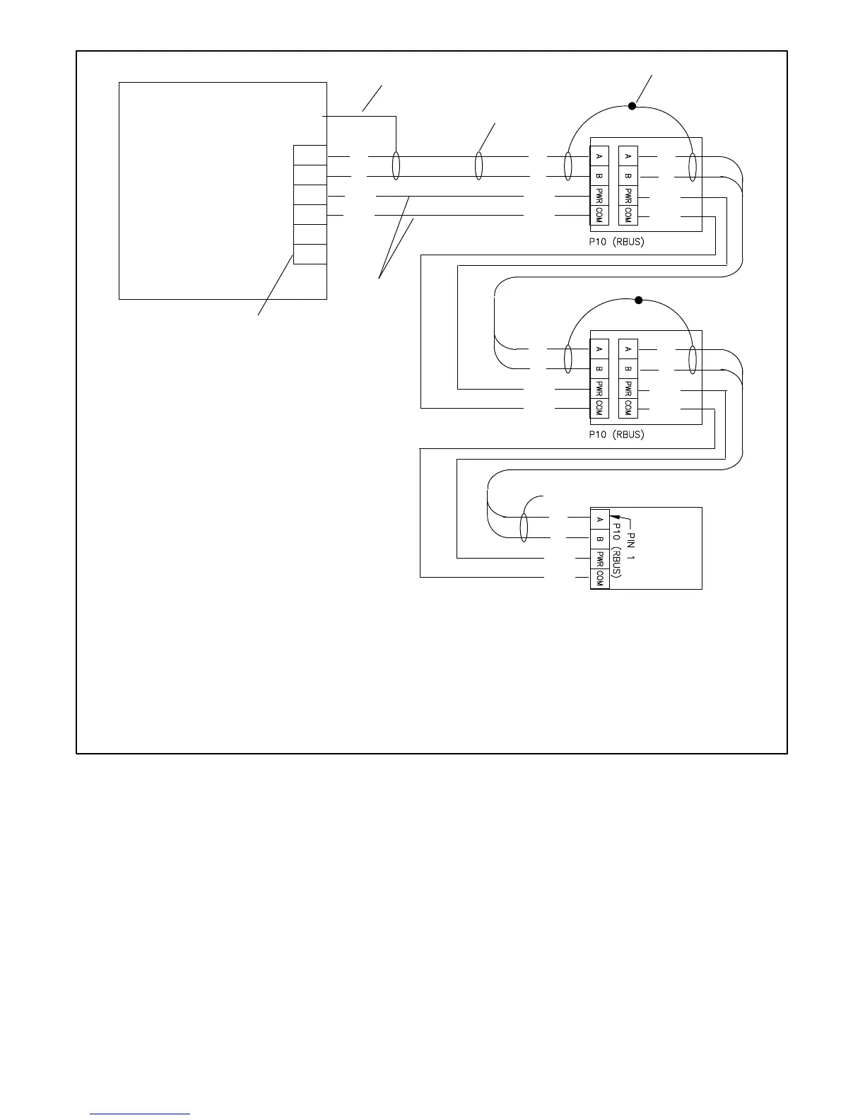
1. Generator set terminal block. See Figure 1-17 for location. Check the decal on the generator set for terminal block connections.
2. Connect one end of each c able shield to GROUND at the generator set.
3. Communication cable Belden #8762 or equivalent 20 AWG shielded, twisted-pair cable (one pair).
4. Connect shields together as shown.
5. Leave one end of each cable shield disconnected at the last device.
6. 12 AWG or 14 AWG leads for PWR and COM.
GND
A
B
COM
PWR
3
4
RBUS
12 VDC
1
2
5
6
Note: Connect A to A, B to B, PWR to PWR, and COM to COM.
See Section 1.10.2, Cable Specifications.
* RXT transfer switch with standard or combined interface/ load management board.
Do not use a load shed kit with a combined interface board.
Load
Shed
Kit
Figure 1-25 Accessory Module Connections with 12--14 AWG Power Leads
 Loading...


