8
TT-1651 4/17a
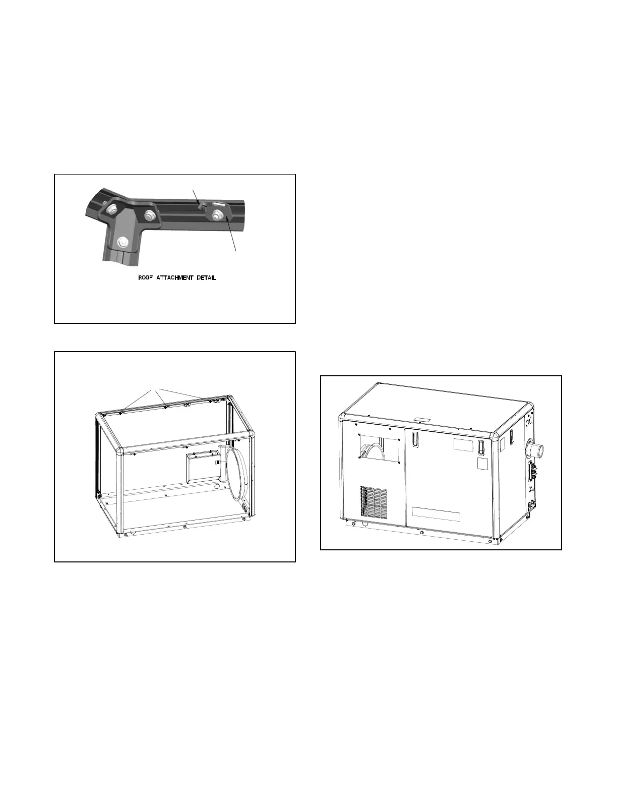
4. Install the roof.
4.1 Install a panel mounting bracket (GM77222 qty. 3)
onto the service-side rail and secure with a
carriage bolt (X-6224-20 qty. 3), and a hex. nut
(X-6210-7 qty. 3). See Figure 16 and Figure 17.
4.2 Use 3 wing nuts (X-276-9) to secure the sound
shield roof (GM89898, or GM90510, or GM90519,
or GM93642) to the panel mounting bracket. See
Figure 16.
GM89548-A
1. Wing nut (X-276-9 qty. 3)
2. Panel mounting bracket (GM77222 qty. 3), carriage bolts
(X-6224-20 qty. 3), and hex. nut (X-6210-7 qty. 3)
2
1
Figure 16 Sound Shield Roof Assembly to Top Rail
1
GM89517-C
1. Panel mounting bracket (GM77222 qty. 3), carriage bolts
(X-6224-20 qty. 3), and hex. nut (X-6210-7 qty. 3)
Bracket Location
on Service Side
Figure 17 Panel Mounting Bracket Location for Roof
5. Install the doors/panels.
5.1 Align the pins to the holes in the mounting
bracket/base and install the controller panel
(GM89881) on the service side of the unit. Secure
the top of the panel to the top rail using 2 screws
(M7985A-05020-20) and 2 washers
(M125A-05-08). Install the decal (GM93648) on
the panel. See Figure 19.
5.2 Align the pins to the holes in the mounting
bracket/base and install the door (GM93560) on
the alternator end of the unit. See Figure 19.
Secure the top of the door to the top rail using
2 screws (M7985A-05020-20) and 2 washers
(M125A-05-08).
5.3 Use the existing hardware on the customer
connection panel (GM93558 or GM95124) to
secure it to the mounting bracket/base. See
Figure 19. Secure the top of the panel using 2
screws (M7985A-05020-20) and 2 washers
(M125A-05-08).
5.4 Align the pins to the holes in the mounting
bracket/base and install the door (GM89877, or
GM90507, or GM90516, or GM93640) on the non
service side of the unit. See Figure 19. Secure
the top of the panel using 3 screws
(M7985A-05020-20) and 3 washers
(M125A-05-08).
5.5 Align the pins to the holes in the mounting
bracket/base and install the door (GM89867, or
GM90504, or GM90513, or GM93638) on the
service side of the unit. See Figure 19.
5.6 Align the pins to the holes in the mounting
bracket/base and install the door (GM93562) on
the engine end of the unit. See Figure 19.
GM93548-A
Figure 18 Sound Shield
6. Restore the generator set to service.
6.1 Reconnect the connectors that were
disconnected in step 1.5. Position the controller
into the controller panel and secure using the
existing hardware and gasket (removed in step
1.6.
6.2 Check that the generator set master switch is in
the OFF position.
6.3 Reconnect the generator set engine starting
battery, the negative (--) lead last.
 Loading...


