149Section 8 Decision-Makerr 3500 ControllerTP-6953 7/19
8.6.3 Installation Procedure
Accidental starting.
Can cause severe injury or death.
Disconnect the battery cables before
working on the generator set.
Remove the negative (- ) lead first
when disconnecting the battery.
Reconnect the negative (- ) lead last
when reconnecting the battery.
WARNING
Disabling the generator set. Accidental starting can
cause severe injury or death. Before working on the
generator set or equipment connected to the set, disable the
generator set as follows: (1) Press the generator set off/reset
button to shut down the generator set. (2) Disconnect the
power to the battery charger, if equipped. (3) Remove the
battery cables, negative (- ) lead first. Reconnect the negative
(- ) lead last when reconnecting the battery. Follow these
precautions to prevent the starting of the generator set by the
remote start/stop switch.
1. Acquire the user parameters.
a. Choose one of the following methods to
retrieve the user parameters:
D Backup disk. If a backup disk was previously made,
obtain the parameters from this disk. If a disk was
not previously made, create a backup if possible
using the SiteTecht software. The existing
controller must function in order to create the file.
D Paper form. Parameters may have been
previously recorded on a User-Defined Settings
form or other similar form.
D Controller menu. Manually review the controller
menu displays if possible and enter the parameter
information in the Decision-Makerr 3500
Operation Manual.
b. Save the user parameter data for step 6c.
2. Remove the generator set from service.
a. Press the generator set master control
OFF/RESET button.
b. Disconnect the power to the battery charger, if
equipped.
c. Disconnect the generator set engine starting
battery(ies), negative (- ) lead first.
3. Remove the existing controller and disconnect the
electrical connections.
a. Remove the junction box panels as needed to
access the wiring.
b. Remove the four controller panel screws.
Note: Clearly mark all disconnected
leads/connectors from the controller
with tape to simplify reconnection.
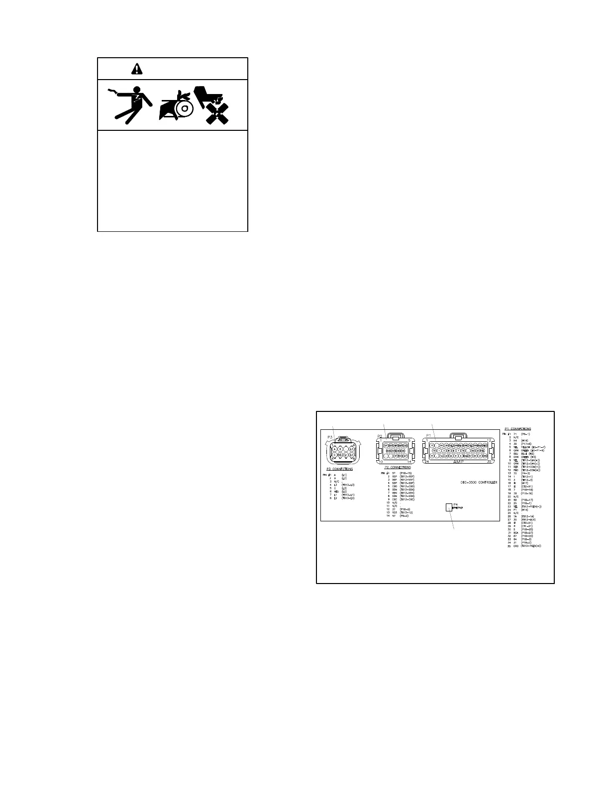
c. Disconnect the controller harness connectors:
P1 (35-Pin) Connector for engine/generator
wiring harness.
P2 (14-Pin) Connector for sensor input
connections and relay driver output
connections.
P3 (8-Pin) Connector for generator set output
voltage sensing and paralleling bus voltage
sensing connections.
P4 (Ethernet) Connector connects to a
network communication line.
Note: These connections are typical and may
not apply to all applications. See the
corresponding wiring diagram found in
the respective wiring diagrams manual.
1. P3 (8-pin) connector
2. P2 (14-pin) connector
3. P1 (35-pin) connector
4. P4 Ethernet connector
GM92288A-A
123
4
Figure 8-5 Main Circuit Board Connectors
4. Reconnect the electrical connections and install
the replacement controller.
a. Reconnect all of the electrical connections
disconnected in step 3.c.
b. Align the controller panel with the mounting
holes and install four screws.
c. Replace the junction box panels if previously
removed.
 Loading...


