TP-6953 7/19 155Section 9 Component Testing and Adjustment
9.2.1 Removal
1. Disconnect wiring from the part(s), noting the
locations from which wiring was removed for later
reconnection. Tape and label the wires as needed.
2. Note the position of the part(s) and loosen or
remove hardware that holds the part(s) in place. If
the removal is complex or will span several days,
make sketches or use a video recorder or digital
camera to help capture t he detail.
Note the location, type, and condition of the
hardware removed and compare it with the parts
list. Replace damaged or missing hardware.
3. Carefully remove the part(s) from the unit. Gently
rock plug-in parts, such as relays, from side to side
while pulling straight out to remove them without
bending the circuit boards.
9.2.2 Installation
1. Position the part(s) in place in the same manner
that the old part was installed. Support the back of
the socket when installing plug-in parts, such as
relays and wiring harness plugs.
2. Tighten or reinstall hardware that holds the part(s)
in place to the general torque specifications in
Appendix C, General Torque Specifications,
unless otherwise noted.
If the torque specifications do not cover the
application or do not seem appropriate let common
sense prevail. Avoid overtorquing hardware in
sheet metal and non-metallic composites.
3. Reconnect wiring to the same location from which it
was removed, torquing terminals to the
specifications given in Section 1, Specifications.
9.3 General Information
Use the respective parts catalog to determine the
appropriate replacement part. Sometimes service kits
replace a given part where additional components in the
kit are necessary to provide the functional component
equivalent. The parts catalog illustrations may serve as
a guide for replacement but be aware that multiple
models are generally illustrated in a single view and
details may not represent the specific application.
9.4 Leads/Wires/Connectors/
Wiring Harnesses
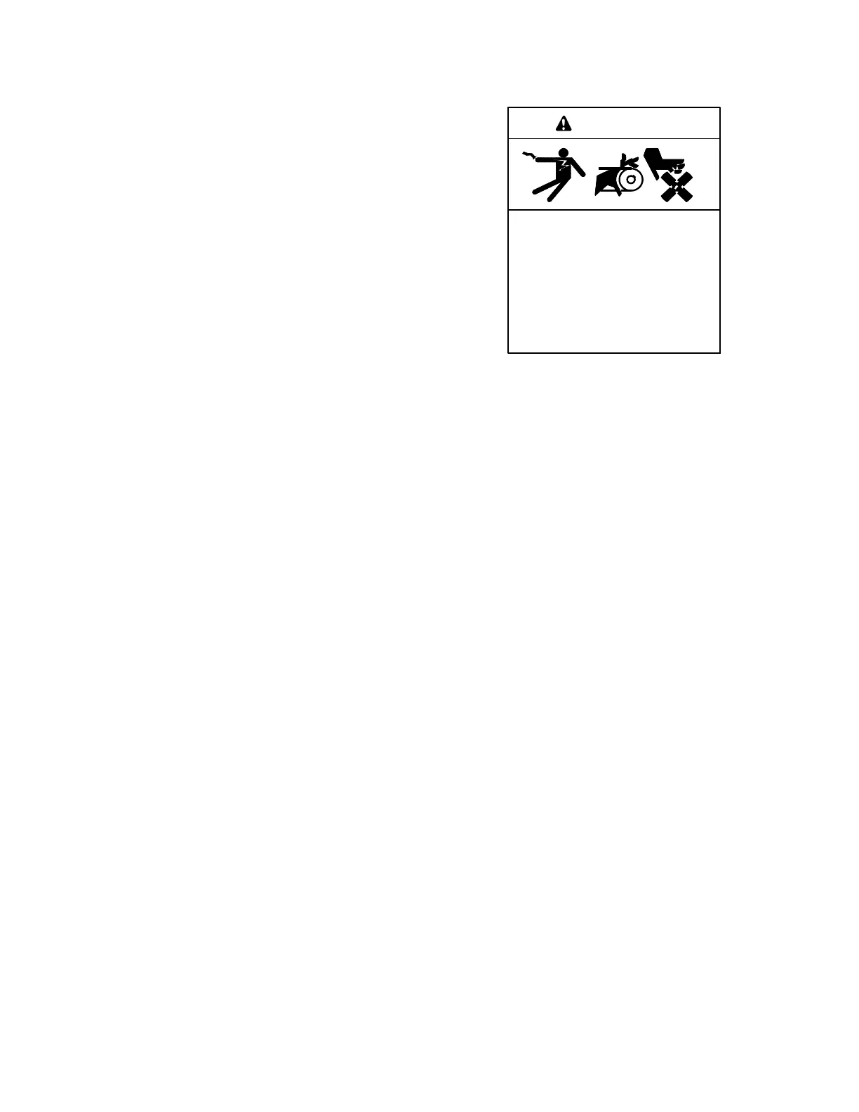
Accidental starting.
Can cause severe injury or death.
Disconnect the battery cables before
working on the generator set.
Remove the negative (- ) lead first
when disconnecting the battery.
Reconnect the negative (- ) lead last
when reconnecting the battery.
WARNING
Disabling the generator set. Accidental starting can
cause severe injury or death. Before working on the
generator set or equipment connected to the set, disable the
generator set as follows: (1) Press the generator set off/reset
button to shut down the generator set. (2) Disconnect the
power to the battery charger, if equipped. (3) Remove the
battery cables, negative (- ) lead first. Reconnect the negative
(- ) lead last when reconnecting the battery. Follow these
precautions to prevent the starting of the generator set by the
remote start/stop switch.
Repair/replace wiring when there is any doubt about its
condition. Tape minor control circuit wire insulation cuts
or abrasions less than 1 mm (0.04 in.) across by
wrapping the section tightly with three layers of electrical
tape.
Repair moderately damaged leads, where conductors
are cut or insulation is damaged over sections shorter
than about 100 mm (4 in.) or less than about 25% of the
length of the wire by cutting out the damaged section
andsplicinginwireofthesametype.
Replace extensively damaged or deteriorated leads
completely. If the leads are part of a wiring harness,
replace entire wiring harness. Fabricate replacement
leads using the same type of wire as the old leads. Add
terminals and lead markers at each end of the new load.
 Loading...


