TP-6953 7/19 157Section 9 Component Testing and Adjustment
9.5 Crank Relay
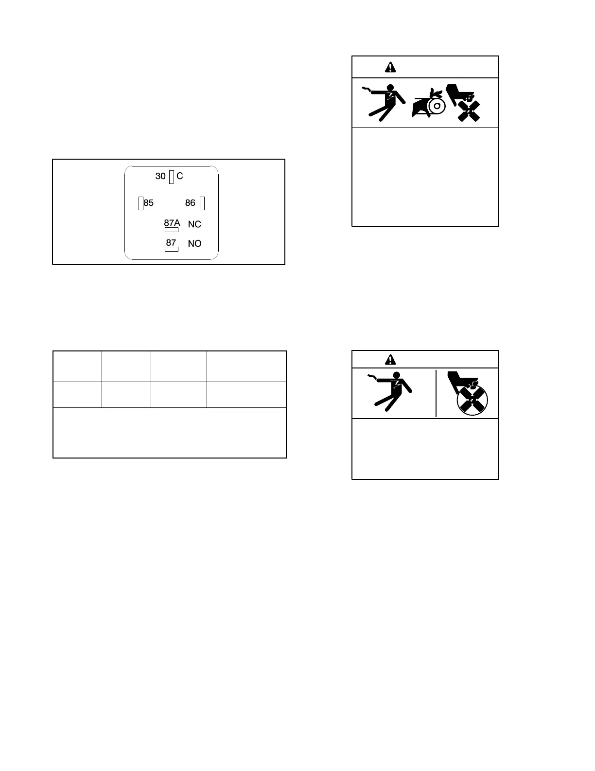
The test procedure for the following crank relay
(Figure 9-6) applies to other applications of the same
type relay including:
D Crank relay
D Run relay
D Cold start relay
D Flash relay
GM14230B-D
Figure 9 -6 Crank Relay Contacts
The relay is a single-pole, double-throw relay. Contacts
85 and 86 are the relay coil. See Figure 9-7 for
specifications by relay part number. If replacement is
necessary, do not substitute part numbers.
Relay Part
Number
Coil
Voltage
VDC
Coil
Resistance,
ohms
NO/NC Contacts
Rating, Amp
GM49746* 12 90 10 50/30
GM49747* 24 360 10 20/15
* These relays contain an integrated diode that may affect
ohmmeter values when checking coil resistance. Be sure to
check coil resistance with the ohmmeter leads connected both
ways to help verify relay functionality and prevent unnecessary
replacement.
Figure 9 -7 Relay Specifications
9.6 Current Transformers
Accidental starting.
Can cause severe injury or death.
Disconnect the battery cables before
working on the generator set.
Remove the negative (- ) lead first
when disconnecting the battery.
Reconnect the negative (- ) lead last
when reconnecting the battery.
WARNING
Disabling the generator set. Accidental starting can
cause severe injury or death. Before working on the
generator set or equipment connected to the set, disable the
generator set as follows: (1) Press the generator set off/reset
button to shut down the generator set. (2) Disconnect the
power to the battery charger, if equipped. (3) Remove the
battery cables, negative (- ) lead first. Reconnect the negative
(- ) lead last when reconnecting the battery. Follow these
precautions to prevent the starting of the generator set by the
remote start/stop switch.
Hazardous voltage.
Can cause severe injury or death.
Operate the generator set only when
all guards and electrical enclosures
areinplace.
Moving parts.
WARNING
Servicing the generator set when it is operating. Exposed
moving parts can cause severe injury or death. Keep
hands, feet, hair, clothing, and test leads away from the belts
and pulleys when the generator set is running. Replace
guards, screens, and covers before operating the generator
set.
9.6.1 Function and Application
The current transformers provide generator set function
including signal/drive for controller sensing of alternator
AC current.
See Figure 9-8. The generator set junction box contains
the stator leads and the current transformers.
 Loading...


