TP-5936 7/04 45Section 10 Voltage Reconnection and Wiring Diagrams
Section 10 Voltage Reconnection and Wiring Diagrams
10.1 4-Lead Reconnection
The following information illustrates the reconnection of
4-lead generator sets. In all cases, follow the National
Electrical Code (NEC).
NOTICE
Voltage reconnection. Affix a notice to the generator set after
reconnecting the set to a voltage different from the voltage on
the nameplate. Order voltage reconnection decal 246242
from an authorized service distributor/dealer.
10.1.1 100--120-Volt Configurations
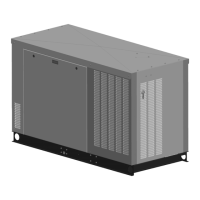
If the installation requires a factory two-pole circuit
breaker, do not connect the load-side terminals of the
circuit breaker together. See Figure 10-1. If the
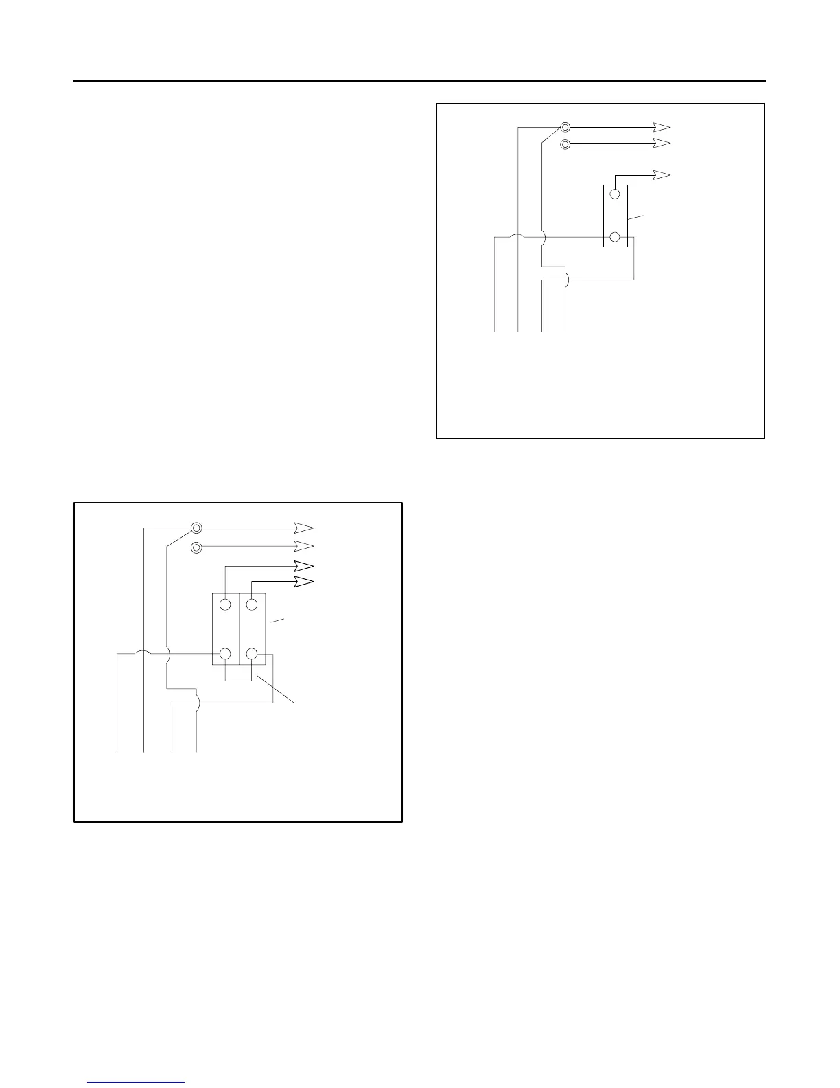
installation requires a 100--120-volt, 2-wire system, use
a single-pole circuit breaker. See Figure 10-2. When
connecting stator phase leads together, size the output
lead (L1) accordingly to handle the amperage. Use a
jumper lead on the line side of the circuit breaker to
balance the load of the generator set.
GRD.
L1
L2
4321
L0 (Neutral)
L0
Ground
Load
Side
Line
Side
Two-Pole
Circuit
Breaker
Jumper
lead
60 Hz 50 Hz
L0--L1 100--120 Volt 100--120 Volt
L0--L2 100--120 Volt 100--120 Volt
Figure 10-1 100--120-Volt, 3-Wire Configuration
4321
Stator Leads
L0
GRD.
L1
L0 (Neutral)
Line
Side
Single-Pole
Circuit
Breaker
Ground
Load
Side
60 Hz 50 Hz
L0--L1 100--120 Volt 100--120 Volt
L0--L2 100--120 Volt 100--120 Volt
Figure 10-2 100--120-Volt, 2-Wire Configuration
 Loading...