TP-5986 4/03 27Section 7 Generator Troubleshooting
7.2 PowerBoosttIIIE Voltage
Regulators
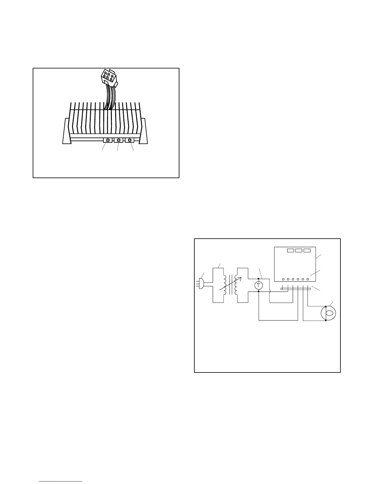
The generator set is equipped with a PowerBoostt IIIE
voltage regulator. See Figure 7-3.
TP-598653
1
3
2
1. Voltage adjustment potentiometer
2. Stability adjustment potentiometer
3. Volts/Hz adjustment potentiometer
Figure 7-3 PowerBoostt IIIE Voltage Regulator
The voltage regulator monitors the output voltage of the
generator set.
The 10-amp regulator fuse protects the alternator stator
windings (power supply) 55-33 from excessive current
draw because of an inoperative voltage regulator or a
downstream short. If the regulator’s 10-amp fuse blows,
the generator set will shut down. Verify that the regulator
fuse is functional before proceeding with the test.
7.2.1 Voltage Regulator Test
Perform the following test to check the regulator output.
Use the following components to test the voltage
regulator:
D Variable transformer, 0--140 volts, 0.5-amp minimum
D Plug, 120 volts AC
D Lamp, 120 volts, 100 watts
D AC voltmeter
D Insulated copper wire, #14 AWG, minimum
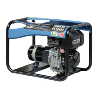
Regulator Test Procedure
1. Connect the components as shown in Figure 7-4.
2. Turn the variable transformer setting to zero. Plug
in the variable transformer.
3. Turn the variable transformer on. Slowly increase
the variable transformer voltage to 100 volts. The
test lamp should light. If the lamp does not light,
turn the voltage adjustment potentiometer (pot)
clockwise. If the lamp still does not light, the
voltage regulator is inoperative. Replace the
voltage regulator. An inoperative voltage regulator
causes a generator no/low-output condition.
4. Slowly increase the voltage to 120 volts. The lamp
should go out and stay out as the voltage
increases. If the lamp remains lit, turn the voltage
adjustment pot counterclockwise. If the lamp still
remains lit, replace the voltage regulator. A voltage
regulator which tests bad causes a generator high
voltage output condition.
5. Turn the variable transformer to zero and unplug
the AC cord.
Note: For applications requiring fine voltage
adjustment, connect a remote rheostat to
voltage regulator terminal 66.
GY
RY
O
W
BK
66 44
33
55
--
+
1
2
3
4
5
6
7
TP-598654
1. 120 volts AC
2. Variable transformer
3. AC voltmeter
4. Voltage regulator PowerBoosttIIIE
5. Stator/rotor connections (for reference only)
6. Lead color
7. 120 volt, 100 watt lamp
Figure 7-4 PowerBoosttIIIE Voltage Regulator Test