TP-5986 4/0334 Section 8 Component Troubleshooting
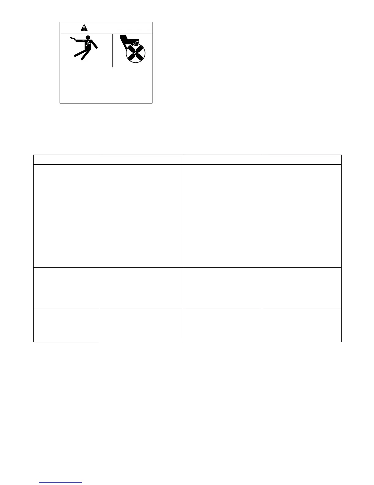
Hazardous voltage.
Can cause severe injury or death.
Operate the generator set only when
all guards and electrical enclosures
areinplace.
Moving rotor.
WARNING
Short circuits. Hazardous voltage/current can cause
severe injury or death. Short circuits can cause bodily injury
and/or equipment damage. Do not contact electrical
connections with tools or jewelry while making adjustments or
repairs. Remove all jewelry before servicing the equipment.
To further check the generator set components,
disconnect the battery and remove the wiring harness
plugs from the controller circuit board. Use an
ohmmeter to check the continuity of the components
and to isolate inoperative components. Refer to
Figure 8-2 and Figure 8-3.
Note: Before performing ohmmeter checks, disconnect
the generator set battery to prevent damage to
the ohmmeter.
Component Ohmmeter Connections Procedure Results
Start/stop switch Connect the ohmmeter to the
P2-6 and P2-4 leads.
Place the ohmmeter on the
R x 1000 scale. Place the
rocker switch in the START
position.
If the switch is functional, zero
ohms continuity. Any
resistance other than zero or
very low ohms, replace the
switch.
Connect the ohmmeter to the
P2-6 and P2-5 leads.
Place the ohmmeter on the
R x 1000 scale. Place the
rocker switch in the STOP
position.
If the switch is functional, zero
ohms continuity. Any
resistance other than zero or
very low ohms, replace the
switch.
K20 relay coil and wiring Connect the ohmmeter t o the
P1-4 and P1-9 leads.
Place the ohmmeter on the
Rx1scale.
If functional, 85 ohms. Low
resistance, shorted C relay
coil and/or wiring. High
resistance, open C relay
and/or wiring.
Starter solenoid
(S relay)
Connect the ohmmeter to the
P4-22 lead and the battery
positive (+) cable. Note:The
J4 and P4 leads must be
disconnected to perform this
test.
Place the ohmmeter on the
Rx1scale.
If functional, approximately
0.5--0.6 ohms at 27_C(80_F)
Controller 10-amp
circuit breaker and
wiring
Connect the ohmmeter to the
battery positive (+) cable and
the P1-14 lead. Note:TheJ4
and P4 leads must be
connected to perform this test.
Place the ohmmeter on the
R x 1000 scale.
If functional, zero or very low
ohms. No reading (infinity),
open circuit or circuit breaker
tripped.
Figure 8-2 Engine/Generator Component Testing, Relay Controller