TP-6137 5/0328 Section 5 Fuel System
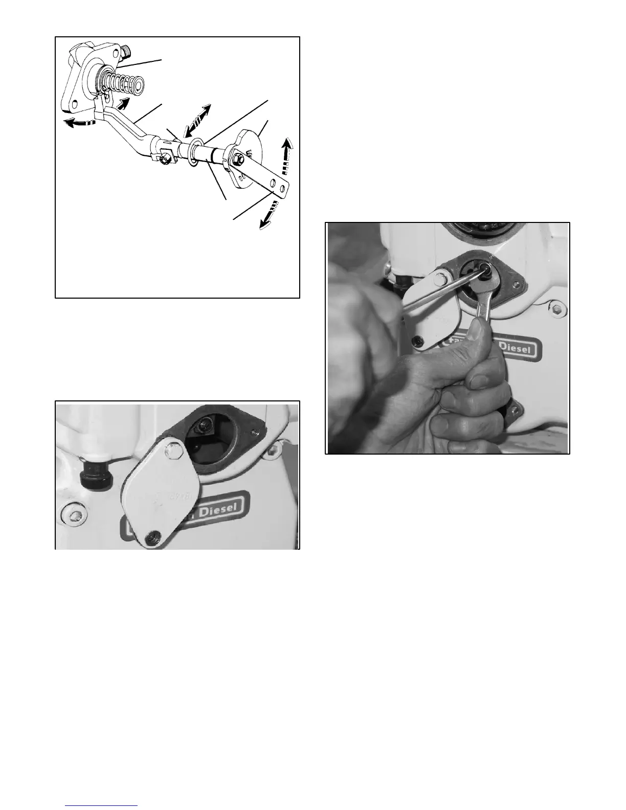
1. Injection pump
2. Control lever
3. Taplet bolt
4. Inner retainer ring
5. Ratchet plate
6. Accelerator lever
7. Eccentric shaft
1
2
3
4
5
6
7
Figure 5-17 Speed Controller Shaft Assembly
Components
Governor and Speed Controller Shaft Adjustment
If the governor or the speed controller shaft has been
removed or tampered with, they need to be readjusted.
Figure 5-18 Cover Plate
1. Remove the governor cover plate on the gear
cover. See Figure 5-18.
2. Move the engine until the governor flyweights are
in the vertical position.
3. Keep the accelerator lever in the higher engine
speed position.
4. Open the lock plate of the taplet bolt and loosen the
nut.
5. Screw the taplet bolt completely until it rests on the
inner control lever.
6. Insert a screwdriver between the flyweights and
force them apart to the maximum opening. See
Figure 5-19.
7. Turn the taplet bolt until it contacts the governor
pin.
Note: No play should be felt when pushing the inner
control lever with the hand.
8. Release the flyweights and turn the taplet bolt a half
turn further.
Figure 5-19 Taplet Bolt Position
9. Hold the taplet bolt in this position and tighten the
nut. See Figure 5-19.
10. Bend the lock plate and reassemble the cover plate
on the gear cover.
Note: It is essential for adequate engine operation to
obtain the correct adjustment between the taplet
bolt and the governor pin. The engine will go into
overspeed if a clearance exists between the
taplet bolt and the governor pin while a forced
contact produces an engine speed drop.
11. With the engine stopped, adjust both the cross
slotted nuts so that their upper surfaces are at the
same height as the governor bolt. See
Figure 5-20.
12. Start the engine and check its speed.