TP-6255 7/06 61Section 7 Controller
9. Disconnect wiring harness plugs P1, P15, and P16
from the ADC controller.
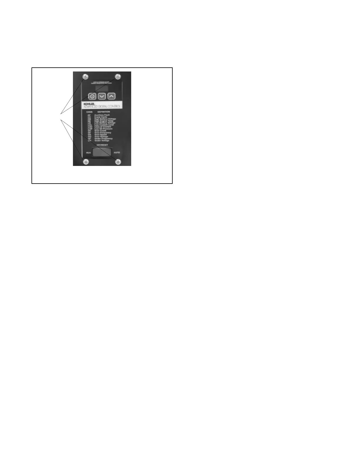
10. Loosen and remove the four controller mounting
screws at the front of the controller. See
Figure 7-17. Remove the controller.
1
tp6196
1. Controller mounting screws (4 ea.)
Figure 7-17 Controller Mounting Screws
11. Place the new controller into position and install the
four mounting screws.
12. Reattach connectors P1, P15, and P16 to the new
controller.
13. Verify that the generator set master switch is in the
OFF position.
14. Reconnect the engine starting battery, negative (--)
lead last.
15. Reconnect power to the battery charger, if
equipped.
16. Follow the instructions in Section 7.5.2 to change
the new controller’s configuration settings to match
the generator set system voltage and frequency,
unit configuration, engine type, engine data input
types, battery voltage, and communications
settings.
17. Use a voltmeter to check the output voltage. Follow
the instructions in Sections 7.5.3, Voltage
Adjustment and 8.8.2, Voltage Adjustment, to
adjust the output voltage and stability.
18. Check the output frequency. Follow the
instructions in Section 4.4, Governor, to adjust the
output frequency.
19. Place the generator set master switch in the AUTO
position if an ATS or remote start/stop switch is
used.
20. Replace the sound shield roof and door(s), if
equipped.
 Loading...


