TP-6255 7/0660 Section 7 Controller
7.11 Controller Replacement
If the troubleshooting procedures in Section 6 identify a
faulty controller, use the procedure in this section for
controller replacement. Always check the controller
configuration, fuse, wiring, and connections before
replacing the controller. For output voltage problems,
replace the SCR module and check the operation again
before replacing the controller.
After replacing the controller, verify that the new
controller’s configuration settings match the generator
set system voltage and frequency, unit configuration,
engine type, engine data input types, battery voltage,
and communications settings. Refer to Section 7.5 for
instructions to check the controller configuration and to
change the settings, if necessary.
After the controller configuration has been checked and
set to match the generator set, use a voltmeter to check
the generator set output voltage. If the output voltage or
frequency needs adjustment, use the voltage
adjustment procedure in Section 8.8.2 and the governor
adjustment instructions in Section 4.4.
ADC 2100 Controller Replacement Procedure
1. Place the generator set master switch in the OFF
position.
2. Disconnect power to the battery charger, if
equipped.
3. Disconnect the generator set engine starting
battery, negative (--) lead first.
Accidental starting.
Can cause severe injury or death.
Disconnect the battery cables before
working on the generator set.
Remove the negative (--) lead first
when disconnecting the battery.
Reconnect the negative (--) lead last
when reconnecting the battery.
WARNING
Sound Shield Equipped Models: For access to the
generator set to perform regular maintenance, remove
the sound shield doors and roof.
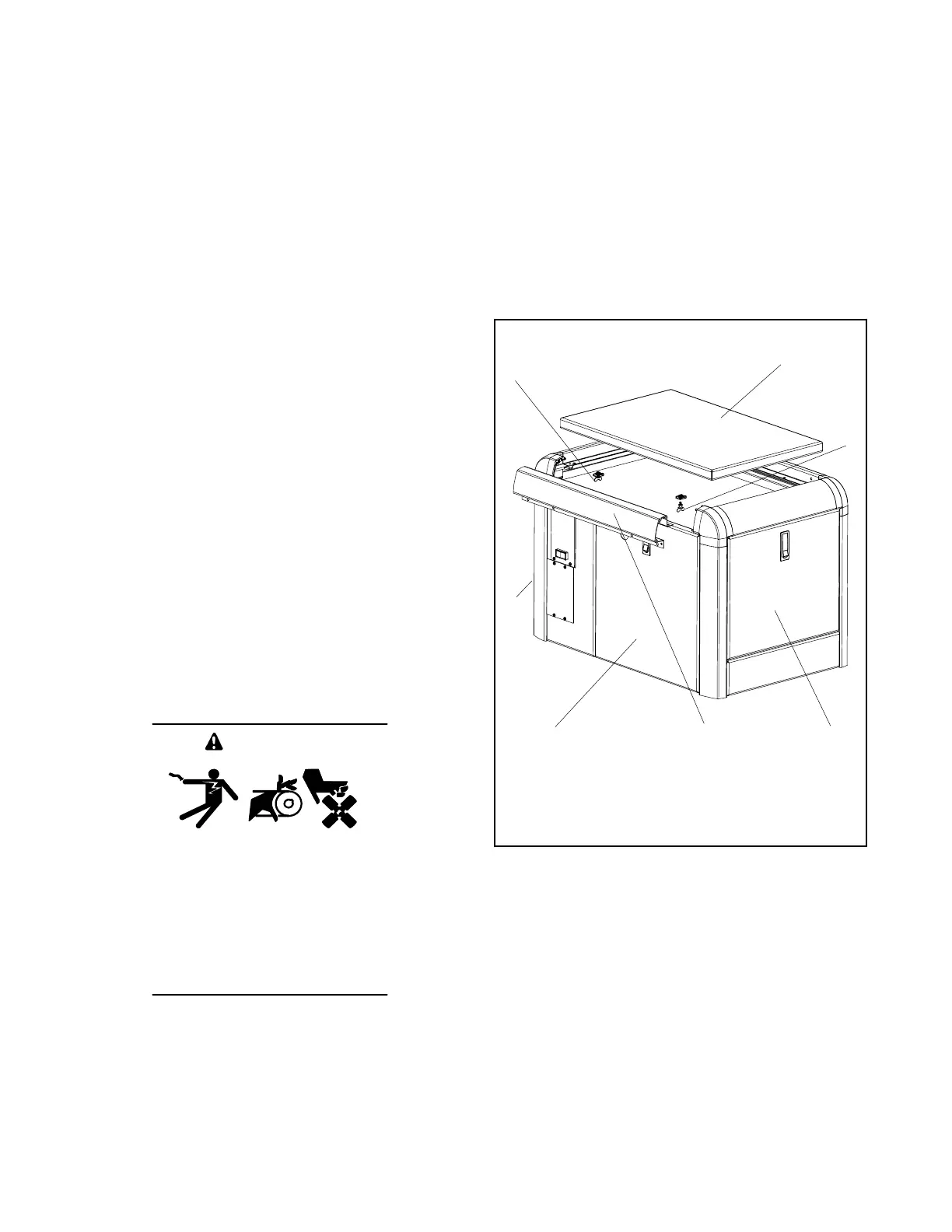
4. Sound-Shielded Models: Open the service-side
door.
5. Sound-Shielded Models: Release the two
quarter-turn fasteners located underneath the roof.
See Figure 7-16.
6. Sound-Shielded Models: Lift up the roof.
7. Sound-Shielded Models: Slide the roof towards
the service side of the unit for removal.
8. Sound-Shielded Models: Open the front, rear,
and non-service side doors as needed.
1
1. Sound shield roof
2. Quarter-turn fastener
3. Alternator-end door
4. Service-side door
5. Front rail
6. Engine-end door
2
2
4
3
5 6
Figure 7-16 Sound Shield Roof Removal
 Loading...


