TP-6255 7/06 71Section 8 Component Testing and Adjustment
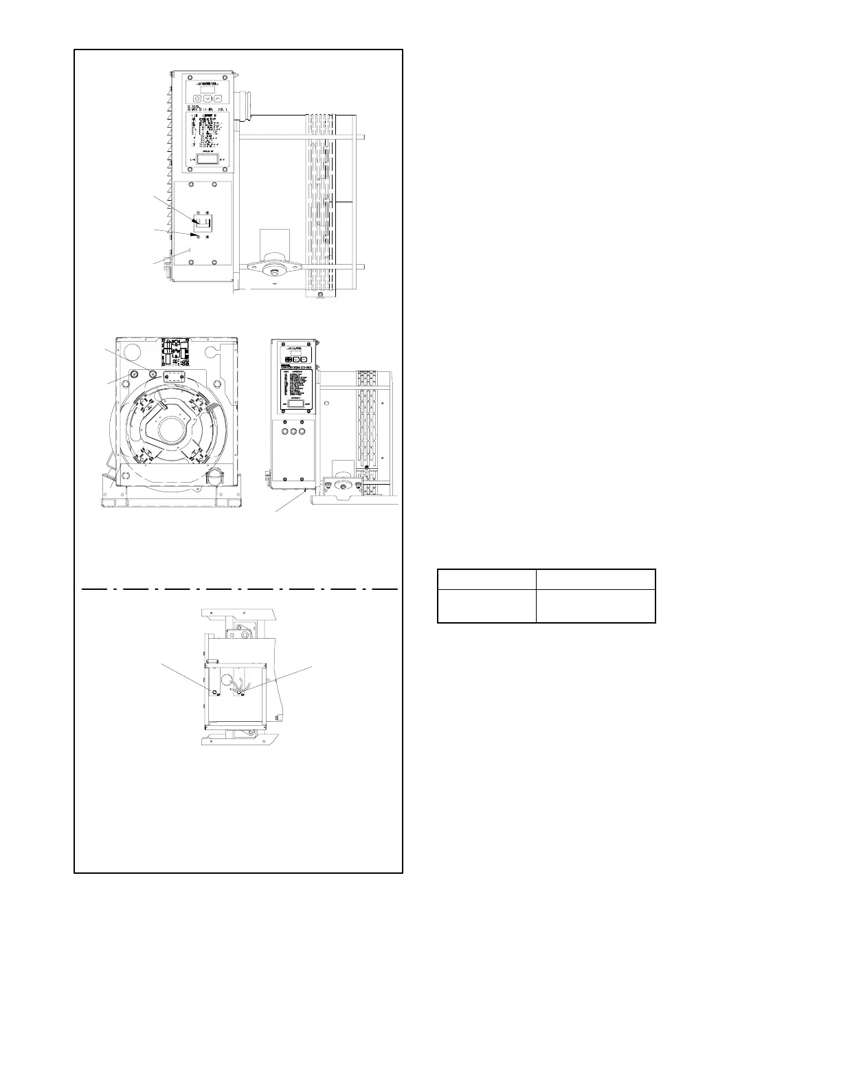
Earlier Models
Generator-End View
(Shown with louvered panel removed)
1
1. Line circuit breaker
2. Circuit breaker mounting hardware
3. Circuit breaker cover plate
4. Load connection terminal L0
5. Ground connection terminal GRD
4, 5
2
3
Top View
(Shown with junction box cover removed)
28/32EOZD Models
8--24EOZD Models
4
5
Service-Side View
8--32EOZD Models, Typical
Later Models
Service-Side View
4
5
Figure 8-16 Circuit Breaker and L0 Terminal Location
5. Check and readjust the voltage if necessary.
6. Set the voltmeter to measure frequency. Adjust the
engine speed to the cut-in frequency shown in
Figure 8-17 by adjusting the governor as described
in Section 4.4.
7. Set the voltmeter to measure voltage. Adjust the
volts/Hz (parameter 3P) until the voltage level
measured by the voltmeter begins to drop. When
set, the generator (as load is applied) attempts to
maintain normal output until the engine speed
drops below the cut-in frequency set in step 6.
8. Set the voltmeter to measure frequency. Adjust the
engine speed to the operating frequency (50 or
60 Hz) by adjusting the engine governor.
9. Readjust the voltage gain (parameter 2P) until the
light flicker minimizes, if necessary.
10. Check the voltage. Readjust the voltage
(parameter 1P), if necessary.
11. Save the settings. Refer to Section 7.5 for
instructions.
Note: The ADC will revert to the previous settings
at the next startup if the changes are not
saved.
12. Stop the generator set.
Frequency Cut-In Frequency
60 Hz 57.5 Hz
50 Hz 47.5 Hz
Figure 8-17 Cut-In Frequencies
 Loading...


