TP-7203 4/23 31
2.9 Accessory Module RBUS Communication Connections
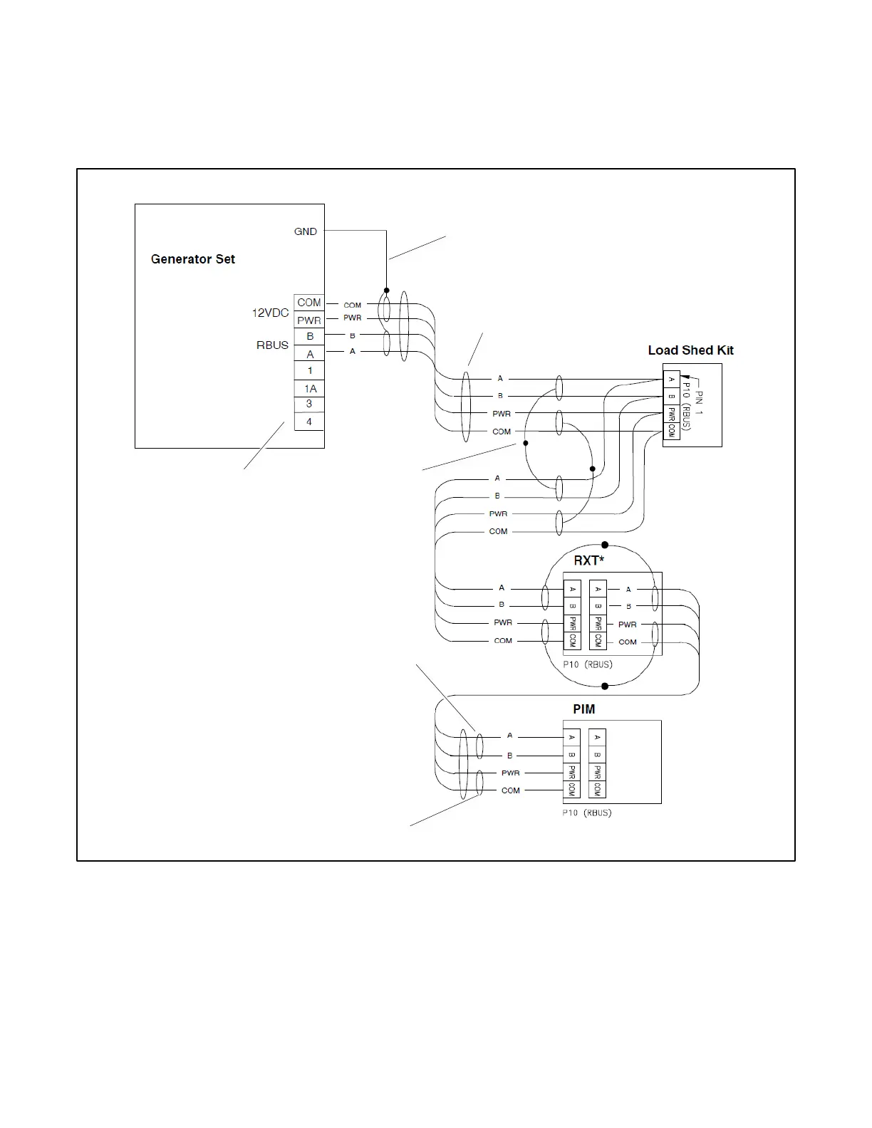
See Figure 16 through Figure 19 for RBUS communication connection options with up to three accessory modules. Accessory
modules can include one Model RXT transfer switch, one programmable interface module (PIM), and/or one load shed kit.
See the Communication Cable Specifications section for cable size and length specifications.
Figure 16 Accessory Module Communication Connection Details
Customer connection terminal
block. Check the decal on the
generator set for terminal block
connections.
Connect one end of each cable shield to
GROUND at the generator set.
Communication cable (1 run shown)
Connect shields
together as shown.
Leave the end of each cable shield
disconnected at the last device.
Leave the end of each cable shield
disconnected at the last device.
Note:
See the Communication Cable Specifications section for
maximum cable lengths.
* RXT transfer switch with standard or combined
interface/load management board. Do not use a load shed
kit with a combined interface board.
 Loading...


