TP-7203 4/23 33
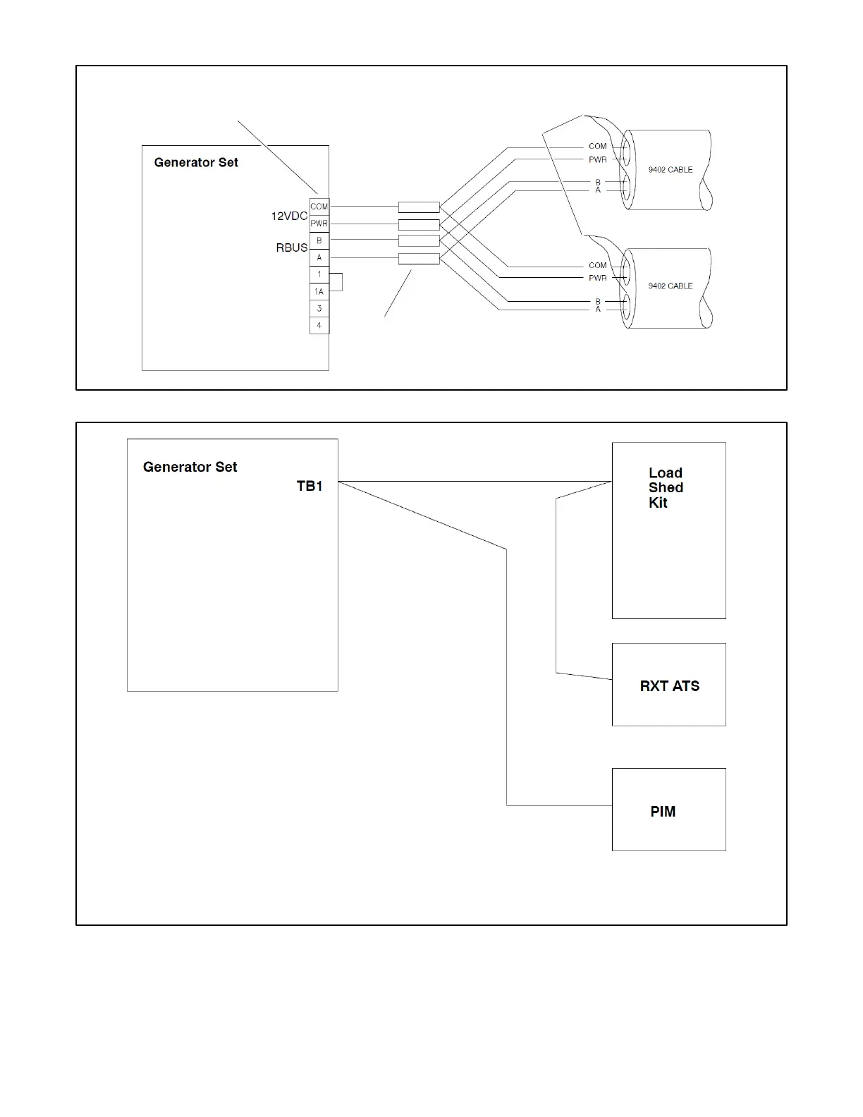
Figure 18 Multiple Connections to the Generator Set
Figure 19 Accessory Module Connections (two cable runs with one and two modules shown)
2.10 Other Accessories
Install and connect optional accessories. Follow the installation instructions provided with the accessory kits. See Accessories
section for more information.
Connect all of the shield leads On this
end to GROUND at the generator set.
Customer connection terminal block. Check the
decal on the generator set for terminal block
connections.
See the Communication Cable Specifications section for cable
• Check the decal on the generator set for terminal block connections.
• See the Communication Cable Specifications section for maximum
total cable length with 12 or 14 AWG wire.
• See Figure 16 for communication connection (A and B, PWR and COM)
details. Connect the cable shield to ground at the generator set.
 Loading...


