TT-1715 2/17 5
2.5 Use rubber grommets and cable ties as necessary
to protect and secure the wiring from sharp
objects, exhaust system, water, and any moving
parts.
2.6 For gasoline-powered generator sets, select a
location as near as practical to the generator
remote digital gauge for mounting warning decal
part number 249494. See Figure 8. The decal
should be visible when starting the generator set
from the remote digital gauge. Before applying the
decal, ensure that the surface is clean and dry.
249494
Figure 8 Decal
3. Restore the generator set to service.
3.1 Check that the generator set is off and stopped.
3.2 Reconnect the generator set engine starting
battery, negative (--) lead last.
3.3 Press the power button to turn the controller on.
4. Set the CAN communications parameter.
The controller must be configured for communication
including gauge operation.
Note: After changing the CAN A communication setting,
power off and then power on the controller .
For generator sets with an ADC II controller: Set the
CAN A parameter to NMEA 2000. Consult the generator
set installation manual for full instructions to set the CAN
A parameter.
For generator sets with an ADC IId controller: Set the
CAN A parameter, under the Gen Set System menu, to
NMEA 2000. Consult the generator set operation
manual for full instructions to set the CAN A parameter.
Configuration Mode
The configuration mode can be selected from any other
mode by pressing and holding the MODE button for
5 seconds. While in the configuration mode, use the
MODE button to select the desired parameter to
change. Currently the gauge supports changing the
gauge I.D. and/or units.
Use the arrow (up) button Y or arrow (down) button B
to set the desired selection.
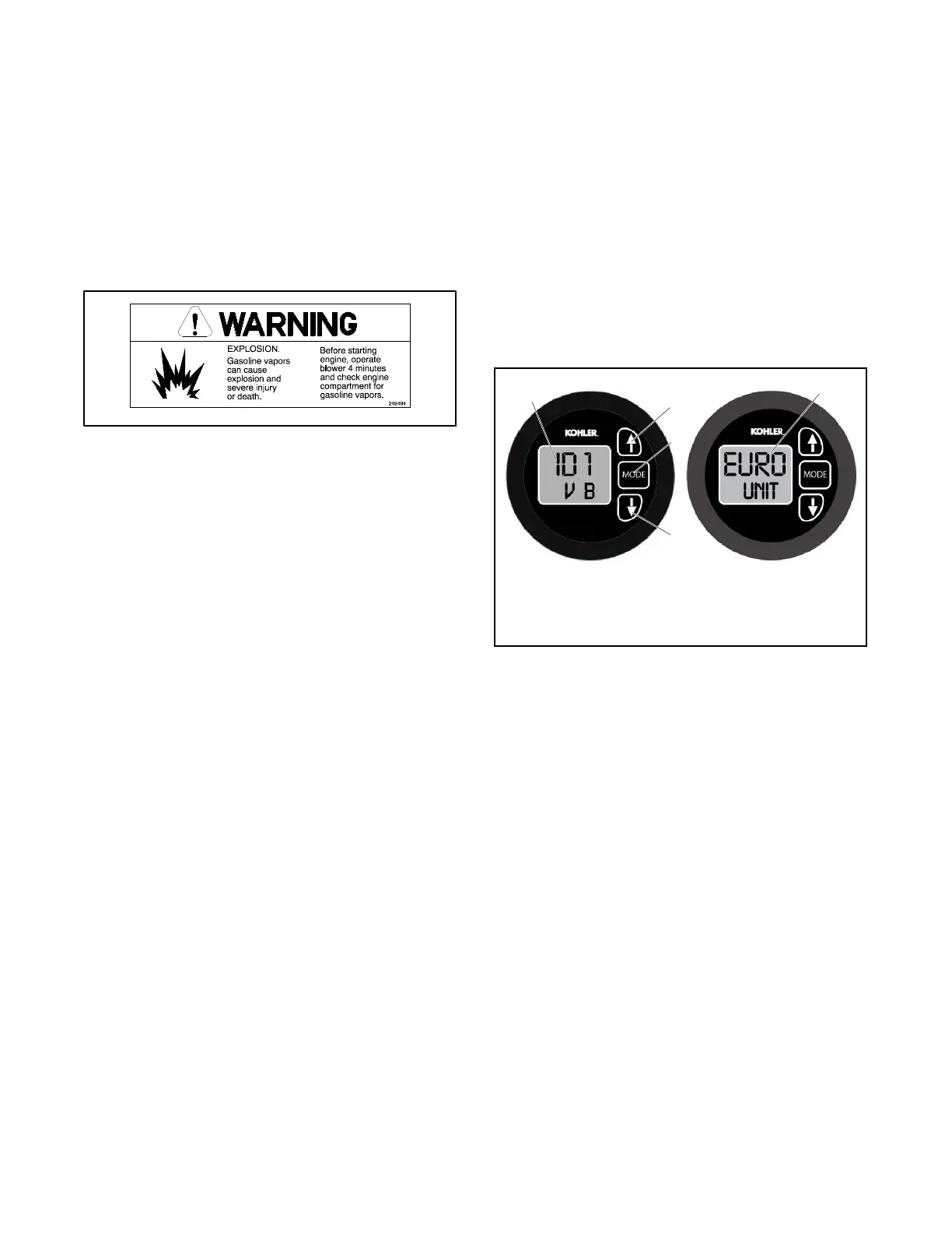
5. Gauge I.D. Configuration Procedure.
5.1 Press and hold the MODE button for 5 seconds to
enter the configuration menu. See Figure 9.
2
1. MODE button
2. START (up) arrow button
3. Address (I.D. number)
4. STOP (down) arrow button
5. Unit selection
1
3
4
5
Figure 9 Configuration Menu Displays
5.2 Use the START arrow (up) button Y or STOP
arrow (down) button B to select the generator set
address 1.
Note: The generator set addresses (I.D.
numbers) 2 thru 4 are reserved for future
use and currently not available.
Note: The gauge’s software version will be
shown on the second line of the I.D.
screen, preceded by the character “V”.
5.3 After all selections have been made, wait
30 seconds before pressing the gauge again to
save the configuration and to exit from the
configuration mode.
 Loading...


