TP-6255 7/0656 Section 7 Controller
1
tp6196
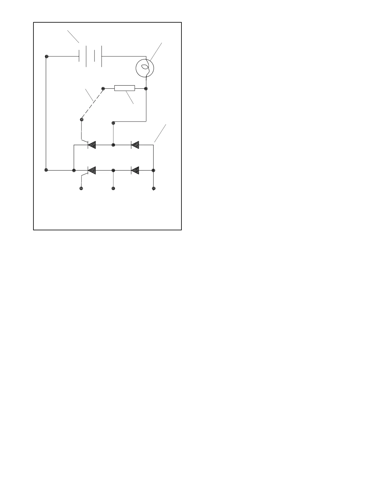
1. 12VDC power source
2. 12 VDC test lamp
3. SCR module
4. Jumper
5. 100--500 ohm resistor
G1
AC2
AC1
G2
(+)
(--)
(+)
(--)
2
3
4
5
Figure 7-12 SCR Test
9. Connect the positive (+) lead from the DC power
source, with the lamp in series, to terminal AC1 on
the SCR module. The lamp should not glow.
10. Connect the jumper, with the resistor in series, from
the positive lead of the DC power source to terminal
G1 on the SCR module. The lamp should glow.
11. Repeat steps 9 and 10, with the positive (+) lead
and lamp connected to terminal AC2 on the SCR
module, and connecting the jumper with resistor to
terminal G2.
12. If any of the above checks indicates a bad SCR
module, replace the module.
 Loading...